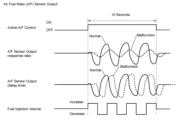
DTC P014C A/F Sensor Slow Response - Rich to Lean Bank 1 Sensor 1 |
DTC P014D A/F Sensor Slow Response - Lean to Rich Bank 1 Sensor 1 |
DTC P014E A/F Sensor Slow Response - Rich to Lean Bank 2 Sensor 1 |
DTC P014F A/F Sensor Slow Response - Lean to Rich Bank 2 Sensor 1 |
DTC P015A A/F Sensor Delayed Response - Rich to Lean Bank 1 Sensor 1 |
DTC P015B A/F Sensor Delayed Response - Lean to Rich Bank 1 Sensor 1 |
DTC P015C A/F Sensor Delayed Response - Rich to Lean Bank 2 Sensor 1 |
DTC P015D A/F Sensor Delayed Response - Lean to Rich Bank 2 Sensor 1 |
| DTC No. | DTC Detection Condition | Trouble Area |
| P014C P014E | The "Rich to Lean response rate deterioration level*" value is less than the standard (2 trip detection logic). |
|
| P014D P014F | The "Lean to Rich response rate deterioration level*" value is more than the standard (2 trip detection logic). | |
| P015A P015C | The "Rich to Lean delay level*" value is less than the standard (2 trip detection logic). | |
| P015B P015D | The "Lean to Rich delay level*" value is more than the standard (2 trip detection logic). |
| Related DTCs | P014C: Air fuel ratio sensor (bank 1) slow response (rich to lean) P014D: Air fuel ratio sensor (bank 1) slow response (lean to rich) P014E: Air fuel ratio sensor (bank 2) slow response (rich to lean) P014F: Air fuel ratio sensor (bank 2) slow response (lean to rich) P015A: Air fuel ratio sensor (bank 1) delayed response (rich to lean) P015B: Air fuel ratio sensor (bank 1) delayed response (lean to rich) P015C: Air fuel ratio sensor (bank 2) delayed response (rich to lean) P015D: Air fuel ratio sensor (bank 2) delayed response (lean to rich) |
| Required Sensors/Components (Main) | Air fuel ratio sensor |
| Required Sensors/Components (Related) | Vehicle speed sensor, crankshaft position sensor |
| Frequency of Operation | Once per driving cycle |
| Duration | 10 to 15 seconds |
| MIL Operation | 2 driving cycles |
| Sequence of Operation | None |
| Monitor runs whenever following DTCs not stored | None |
| Active air fuel ratio control | Executing |
| Active air fuel ratio control is performed when the following conditions are met | - |
| Battery voltage | 11 V or higher |
| Engine coolant temperature | 75°C (167°F) or higher |
| Idle | OFF |
| Engine speed | 1000 to 4000 rpm |
| Air fuel ratio sensor status | Activated |
| Fuel-cut | OFF |
| Engine load | 10 to 70% |
| Shift position | 2nd or higher |
| Catalyst monitor | Not executed |
| Mass airflow | 4 to 15 gm/sec |
| Rich to Lean response rate deterioration level | 0.04 V or less |
| Lean to Rich response rate deterioration level | -0.044 V or higher |
| Rich to Lean delay level | 294.912 ms or more |
| Lean to Rich delay level | 294.912 ms or more |
| Techstream Display | Description |
| NORMAL |
|
| ABNORMAL |
|
| INCOMPLETE |
|
| N/A |
|
| 1.CHECK FOR ANY OTHER DTCS OUTPUT (IN ADDITION TO DTC P014C, P014D, P014E, P014F, P015A, P015B, P015C OR P015D) |
Connect the Techstream to the DLC3.
Turn the ignition switch to ON.
Turn the Techstream on.
Enter the following menus: Powertrain / Engine and ECT / Trouble Codes.
Read the DTCs.
| Result | Proceed to |
| DTC P014C, P014D, P014E, P014F, P015A, P015B, P015C or P015D is output | A |
| DTC P014C, P014D, P014E, P014F, P015A, P015B, P015C or P015D and other DTCs are output | B |
|
| ||||
| A | |
 |
| 2.INSPECT AIR FUEL RATIO SENSOR (HEATER RESISTANCE) |
Inspect the air fuel ratio sensor (Click here).
|
| ||||
| OK | |
|
| 3.CHECK HARNESS AND CONNECTOR (AIR FUEL RATIO SENSOR - ECM) |
Disconnect the air fuel ratio sensor connector.
Disconnect the ECM connector.
Measure the resistance according to the value(s) in the table below.
| Tester Connection | Condition | Specified Condition |
| D33-1 (HA1A) - D74-22 (HA1A) | Always | Below 1 Ω |
| D33-3 (A1A+) - D74-126 (A1A+) | Always | Below 1 Ω |
| D33-4 (A1A-) - D74-125 (A1A-) | Always | Below 1 Ω |
| D34-1 (HA2A) - D74-20 (HA2A) | Always | Below 1 Ω |
| D34-3 (A2A+) - D74-103 (A2A+) | Always | Below 1 Ω |
| D34-4 (A2A-) - D74-102 (A2A-) | Always | Below 1 Ω |
| D33-1 (HA1A) or D74-22 (HA1A) - Body ground | Always | 10 kΩ or higher |
| D33-3 (A1A+) or D74-126 (A1A+) - Body ground | Always | 10 kΩ or higher |
| D33-4 (A1A-) or D74-125 (A1A-) - Body ground | Always | 10 kΩ or higher |
| D34-1 (HA2A) or D74-20 (HA2A) - Body ground | Always | 10 kΩ or higher |
| D34-3 (A2A+) or D74-103 (A2A+) - Body ground | Always | 10 kΩ or higher |
| D34-4 (A2A-) or D74-102 (A2A-) - Body ground | Always | 10 kΩ or higher |
|
| ||||
| OK | |
|
| 4.INSPECT AIR FUEL RATIO SENSOR |
Check that the proper air fuel ratio sensor is installed to the vehicle.
|
| ||||
| OK | |
|
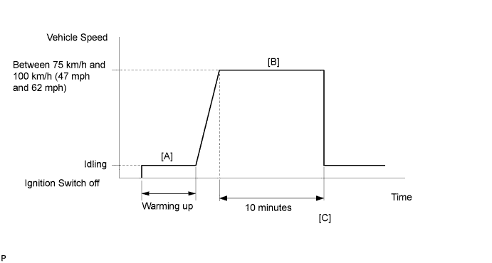
| 5.PERFORM CONFIRMATION DRIVING PATTERN |
Drive the vehicle according to Confirmation Driving Pattern.
| NEXT | |
|
| 6.CHECK WHETHER DTC OUTPUT RECURS (DTC P014C, P014D, P014E, P014F, P015A, P015B, P015C OR P015D) |
Connect the Techstream to the DLC3.
Turn the ignition switch to ON.
Turn the Techstream on.
Enter the following menus: Powertrain / Engine and ECT / Trouble Codes / Pending.
Read the DTCs.
| Result | Proceed to |
| DTC P014C, P014D, P014E, P014F, P015A, P015B, P015C or P015D is output | A |
| No DTC is output | B |
|
| ||||
| A | |
|
| 7.REPLACE AIR FUEL RATIO SENSOR |
Replace the air fuel ratio sensor (Click here).
| NEXT | |
|
| 8.PERFORM CONFIRMATION DRIVING PATTERN |
Drive the vehicle according to Confirmation Driving Pattern.
| NEXT | |
|
| 9.CHECK WHETHER DTC OUTPUT RECURS (DTC P014C, P014D, P014E, P014F, P015A, P015B, P015C or P015D) |
Connect the Techstream to the DLC3.
Turn the ignition switch to ON.
Turn the Techstream on.
Enter the following menus: Powertrain / Engine and ECT / Trouble Codes / Pending.
Read the DTCs.
| Result | Proceed to |
| No DTC is output | A |
| DTC P014C, P014D, P014E, P014F, P015A, P015B, P015C or P015D is output | B |
|
| ||||
| A | ||
 | ||
| ||
