 |
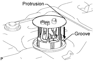
Align the protrusion of the pump and gauge tube with the groove of the fuel tank assembly.
FUEL PUMP > INSTALLATION |
| 1. INSTALL FUEL SUCTION WITH PUMP AND GAUGE TUBE ASSEMBLY |
Apply a light coat of gasoline to a new gasket, and install it to the fuel tank assembly.
|
Align the protrusion of the pump and gauge tube with the groove of the fuel tank assembly.
Install the fuel suction with pump and gauge tube into the fuel tank assembly.
Put the retainer on the fuel tank assembly. While holding the fuel suction with pump and gauge tube, tighten the retainer one complete turn by hand.
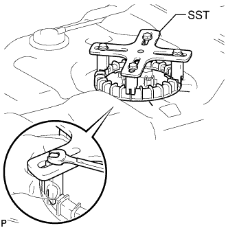 |
Set SST on the retainer.
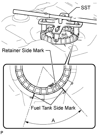 |
Using SST, tighten the retainer until the mark on the retainer is within range A on the fuel tank assembly as shown in the illustration.
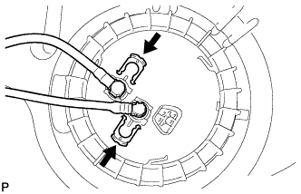 |
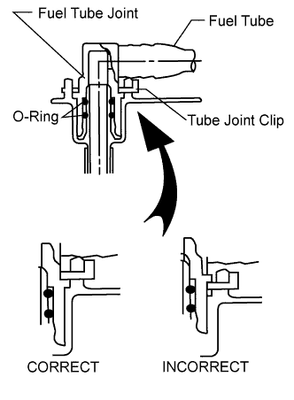
Install the fuel tank main tube sub-assembly and fuel tank return tube with the 2 tube joint clips.
 |
| 2. INSTALL FUEL TANK ASSEMBLY |
Set the fuel tank assembly on a mission jack and raise the fuel tank assembly.
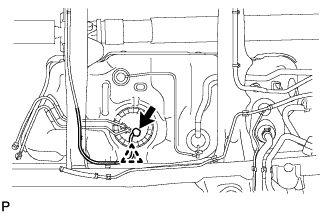 |
Connect the harness clamp and fuel pump connector to the fuel tank assembly.
w/ Cover:
Attach the 3 claws to install the No. 2 fuel tank protector.
Raise the mission jack.
Install the No. 1 fuel tank band sub-assembly and No. 2 fuel tank band sub-assembly with the 2 pins and 2 clips.
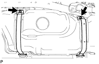 |
Connect the No. 1 fuel tank band sub-assembly and No. 2 fuel tank band sub-assembly with the 2 bolts.
| 3. CONNECT OUTLET NO. 1 CANISTER HOSE |
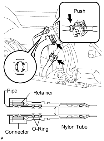 |
Connect the outlet No. 1 canister hose to the inlet fuel tank pipe sub-assembly.
Attach the hose to the No. 1 breather tube clamp.
| 4. CONNECT FUEL TANK TO FILLER PIPE HOSE |
Connect the fuel tank to filler pipe hose to the inlet fuel tank pipe sub-assembly.
Connect the fuel tank breather tube to the inlet fuel tank pipe sub-assembly.
Attach the lock claws to the connector by pushing down on the cover as shown in the illustration.
Attach the filler pipe hose and fuel tank breather tube to the No. 1 breather tube clamp.
| 5. CONNECT FUEL TANK TO CANISTER TUBE |
Connect the fuel tank to filler pipe hose to the inlet fuel tank pipe sub-assembly.
Connect the fuel tank breather tube to the inlet fuel tank pipe sub-assembly.
Attach the lock claws to the connector by pushing down on the cover as shown in the illustration.
Attach the filler pipe hose and fuel tank breather tube to the No. 1 breather tube clamp.
| 6. CONNECT WIRE HARNESS |
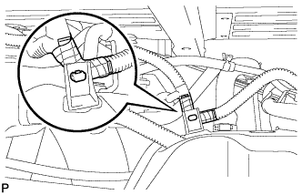 |
Attach the harness clamp to the fuel tank assembly.
| 7. CONNECT VENT LINE HOSE |
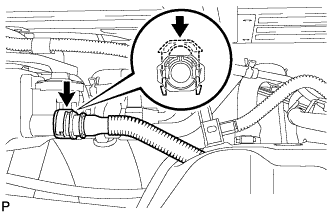 |
Connect the vent line hose and install the retainer.
| 8. CONNECT FUEL TANK RETURN TUBE |
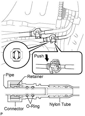 |
Connect the fuel tank return tube.
Attach the lock claws to the connector by pushing down on the cover as shown in the illustration.
| 9. CONNECT FUEL TANK MAIN TUBE SUB-ASSEMBLY |
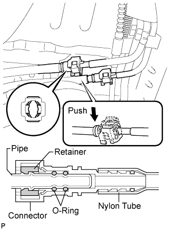 |
Connect the fuel tank main tube.
Attach the lock claws to the connector by pushing down on the cover as shown in the illustration.
| 10. INSTALL NO. 1 FUEL TANK PROTECTOR SUB-ASSEMBLY (for Rough Road Area Specification Vehicles) |
Install the No. 1 fuel tank protector sub-assembly with the 2 bolts and 2 nuts.
| 11. INSTALL FUEL TANK CAP |
| 12. CONNECT CABLE TO NEGATIVE BATTERY TERMINAL |
| 13. INSPECT FOR FUEL LEAK |
Connect the Techstream to the DLC3.
Turn the ignition switch to ON and Techstream main switch on.
Enter the following menus: Powertrain / Engine and ECT / Active Test / Control the Fuel Pump / Speed.
Check that there are no fuel leaks after doing maintenance anywhere on the fuel system.