Measure the resistance according to the value(s) in the table below.
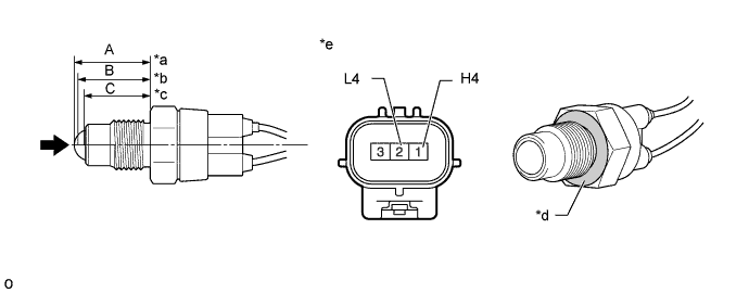
- Dimension (A):
- 24.63 to 24.89 mm (0.970 to 0.979 in.)
- Dimension (B):
- 23.85 to 24.26 mm (0.939 to 0.955 in.)
- Dimension (C):
- 21.89 to 22.40 mm (0.862 to 0.881 in.)
| *a | Switch Condition A (4HI Position) |
| *b | Switch Condition B (Not 4HI / Not 4LO Position) |
| *c | Switch Condition C (4LO Position) |
| *d | Ground Position |
| *e | Component without harness connected (Transfer Indicator Switch) |
- Standard Resistance:
Tester Connection Switch Condition Specified Condition 1 (H4) - Case GND Switch Condition A (4HI Position) 10 kΩ or higher 2 (L4) - Case GND 10 kΩ or higher 1 (H4) - Case GND Switch Condition B (4HI to 4LO Position) Below 1 Ω 2 (L4) - Case GND 10 kΩ or higher 1 (H4) - Case GND Switch Condition C (4LO Position) Below 1 Ω 2 (L4) - Case GND Below 1 Ω
- HINT:
- The ground is the nut of the transfer indicator switch (connecting surface with the transfer case).