 |
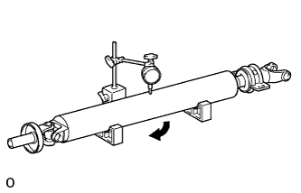
Using a dial indicator, measure the intermediate shaft runout.
- Maximum runout:
- 0.61 mm (0.0240 in.)
PROPELLER SHAFT ASSEMBLY (for 2WD) > INSPECTION |
| 1. INSPECT PROPELLER SHAFT WITH CENTER BEARING ASSEMBLY |
|
Using a dial indicator, measure the intermediate shaft runout.
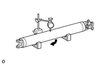 |
Using a dial indicator, measure the propeller shaft runout.
| 2. INSPECT PROPELLER SHAFT UNIVERSAL JOINT SPIDER BEARING |
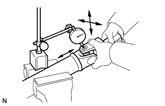 |
Mount the propeller shaft in a vise.
Inspect the spider bearing for wear or damage.
Using a dial indicator, measure the spider bearing axial play by turning the yoke of the flange while holding the shaft tightly.
| 3. INSPECT NO. 1 CENTER SUPPORT BEARING ASSEMBLY |
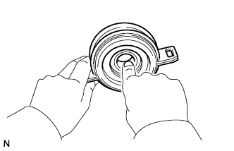 |
Check that the bearing turns freely.
If the bearing is damaged, worn, or does not turn freely, replace it.