 |
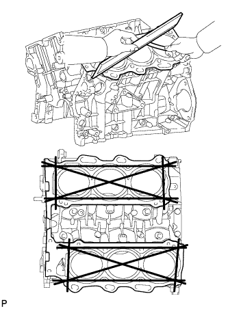
Using a precision straightedge and feeler gauge, measure the warpage of the surfaces which contact the cylinder head gaskets.
- Maximum warpage:
- 0.05 mm (0.00197 in.)
CYLINDER BLOCK > INSPECTION |
| 1. CLEAN CYLINDER BLOCK SUB-ASSEMBLY |
Using a gasket scraper, remove all the gasket material from the top surface of the cylinder block.
Using a soft brush and solvent, thoroughly clean the cylinder block.
| 2. INSPECT CYLINDER BLOCK FOR WARPAGE |
|
Using a precision straightedge and feeler gauge, measure the warpage of the surfaces which contact the cylinder head gaskets.
Visually check the cylinder for vertical scratches. If deep scratches are present, rebore all 6 cylinders.
If necessary, replace the cylinder block.
| 3. INSPECT CYLINDER BORE |
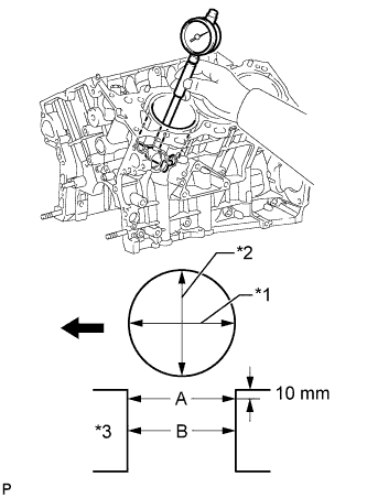 |
Using a cylinder gauge, measure the cylinder bore diameter at positions A and B in the thrust and axial directions.
| *1 | Axial Direction |
| *2 | Thrust Direction |
| *3 | Center |
 | Engine Front |
| 4. INSPECT RING GROOVE CLEARANCE |
Using a feeler gauge, measure the clearance between a new piston ring and the wall of the ring groove.
| Item | Specified Condition |
| No. 1 compression ring | 0.02 to 0.07 mm (0.000787 to 0.00276 in.) |
| No. 2 compression ring | 0.02 to 0.06 mm (0.000787 to 0.00236 in.) |
| Oil Ring | 0.07 to 0.15 mm (0.00276 to 0.00590 in.) |
| 5. INSPECT PISTON RING END GAP |
Insert the piston ring into the cylinder bore.
Using a piston, push the piston ring a little beyond the bottom of the ring travel, 110 mm (4.33 in.) from the top of the cylinder block.
Using a feeler gauge, measure the end gap.
| Item | Specified Condition |
| No. 1 compression ring | 0.22 to 0.32 mm (0.00866 to 0.0126 in.) |
| No. 2 compression ring | 0.35 to 0.45 mm (0.0138 to 0.0177 in.) |
| Oil Ring (Side Rail) | 0.10 to 0.40 mm (0.00394 to 0.0157 in.) |
| Item | Specified Condition |
| No. 1 compression ring | 1.0 mm (0.0394 in.) |
| No. 2 compression ring | 1.1 mm (0.0433 in.) |
| Oil Ring (Side Rail) | 1.0 mm (0.0394 in.) |
| 6. CLEAN PISTON WITH PIN SUB-ASSEMBLY |
Clean the piston.
Using a gasket scraper, remove the carbon from the piston top.
Using a groove cleaning tool or broken ring, clean the piston ring grooves.
Using solvent and a brush, thoroughly clean the piston.
| 7. INSPECT PISTON OIL CLEARANCE |
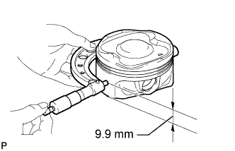 |
Using a micrometer, measure the piston diameter at a position that is 9.9 mm (0.390 in.) from the bottom of the piston (refer to the illustration).
Subtract the piston diameter measurement from the cylinder bore diameter measurement.
| 8. INSPECT PISTON PIN OIL CLEARANCE |
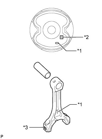 |
Check each mark on the piston and connecting rod.
| *1 | Front Mark |
| *2 | Position Pin Hole Inside Diameter Mark |
| *3 | Connecting Rod Bush Inside Diameter Mark |
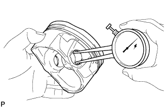 |
Using a caliper gauge, measure the inside diameter of the piston pin hole.
| Item | Specified Condition |
| Mark A | 22.001 to 22.004 mm (0.86618 to 0.86630 in.) |
| Mark B | 22.005 to 22.007 mm (0.86634 to 0.86642 in.) |
| Mark C | 22.008 to 22.010 mm (0.86645 to 0.86653 in.) |
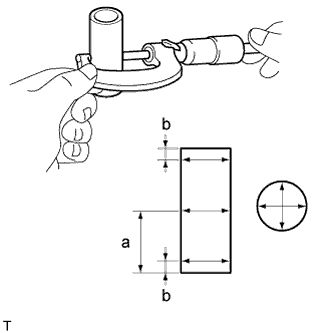 |
Using a micrometer, measure the piston pin diameter.
| Measurement Position | Piston Pin Position |
| a | 28 mm (1.102 in.) from edge |
| b | 5 mm (0.197 in.) from edge |
| Item | Specified Condition |
| Mark A | 21.997 to 22.000 mm (0.86602 to 0.86614 in.) |
| Mark B | 22.001 to 22.003 mm (0.86618 to 0.86626 in.) |
| Mark C | 22.004 to 22.006 mm (0.86630 to 0.86642 in.) |
Using a caliper gauge, measure the inside diameter of the connecting rod bush.
| Item | Specified Condition |
| Mark A | 22.005 to 22.008 mm (0.86634 to 0.86645 in.) |
| Mark B | 22.009 to 22.011 mm (0.86649 to 0.86657 in.) |
| Mark C | 22.012 to 22.014 mm (0.86661 to 0.86669 in.) |
Subtract the piston pin diameter measurement from the piston pin hole diameter measurement.
Subtract the piston pin diameter measurement from the bush inside diameter measurement.
| 9. INSPECT CONNECTING ROD SUB-ASSEMBLY |
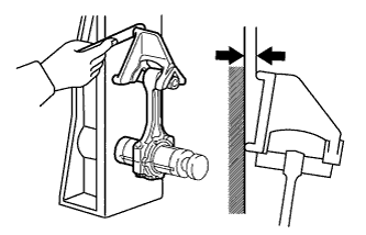 |
Using a rod aligner and feeler gauge, check the connecting rod alignment.
Check for bend.
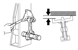 |
Check for twist.
| 10. INSPECT CRANKSHAFT |
Using a dial indicator, measure the runout at the center journal.
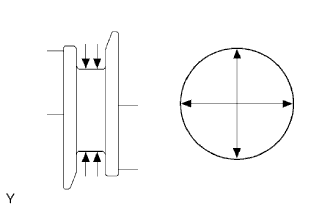 |
Using a micrometer, measure the diameter of each main journal.
Check each main journal for taper and out-of-round as shown in the illustration.
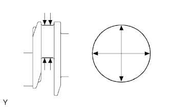 |
Using a micrometer, measure the diameter of each crank pin.
Check each crank pin for taper and out-of-round as shown in the illustration.
| 11. INSPECT CONNECTING ROD BOLT |
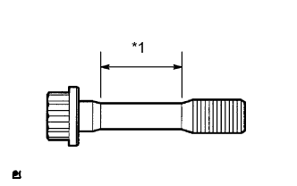 |
Using a vernier caliper, measure the tension portion diameter of the bolt.
| *1 | Measurement Area |
| 12. INSPECT CRANKSHAFT BEARING CAP SET BOLT |
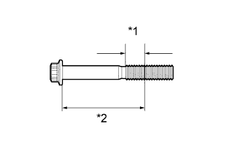 |
Using a vernier caliper, measure the thread outside diameter of the crankshaft bearing cap set bolt.
| *1 | Measurement Area |
| *2 | Distance |
| 13. INSPECT NO. 1 OIL NOZZLE SUB-ASSEMBLY |
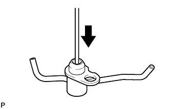 |
Push the check valve with a pin to check if it is stuck. If stuck, replace the oil nozzle.
Push the check valve with a pin to check if it moves smoothly.
If it does not move smoothly, clean or replace the oil nozzle.
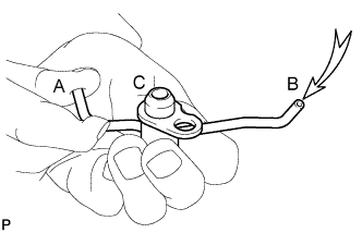 |
While covering A, blow air into B. Check that air does not leak through C. Perform the check again while covering B and blowing air into A.
If air leaks, clean or replace the oil nozzle.
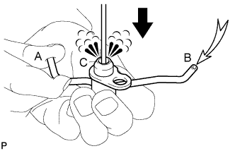 |
Push the check valve while covering A, and blow air into B. Check that air passes through C. Perform the check again while covering B, pushing the check valve and blowing air into A.
If air does not pass through C, clean or replace the oil nozzle.