 |
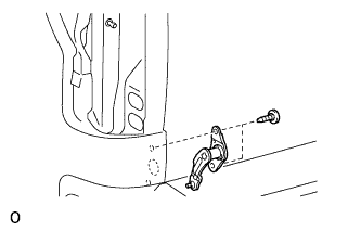
Using a T40 "TORX" wrench, install the tail gate lock male hinge sub-assembly with the 2 screws.
- Torque:
- 29 N*m{ 296 kgf*cm , 21 ft.*lbf }
TAIL GATE > INSTALLATION |
| 1. INSTALL TAIL GATE MALE HINGE SUB-ASSEMBLY LH |
|
Using a T40 "TORX" wrench, install the tail gate lock male hinge sub-assembly with the 2 screws.
| 2. INSTALL TAIL GATE MALE HINGE SUB-ASSEMBLY RH |
Using a T40 "TORX" wrench, install the tail gate lock male hinge sub-assembly with the 2 screws.
| 3. INSTALL TAIL GATE HINGE ASSEMBLY LH |
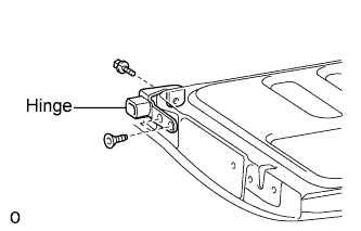 |
Using a T40 "TORX" wrench, install the tail gate hinges to the tail gate with the 2 screws.
Install the bolt to the tail gate.
| 4. INSTALL TAIL GATE HINGE ASSEMBLY RH |
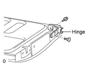 |
Using a T40 "TORX" wrench, install the tail gate hinges to the tail gate with the 2 screws.
Install the bolt to the tail gate.
| 5. INSTALL REAR BODY TAIL GATE ASSEMBLY |
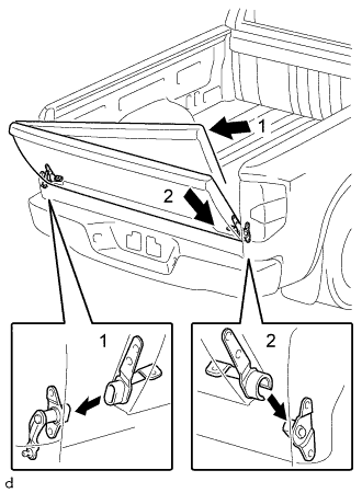 |
Move the tail gate in the direction of arrow 1 in the illustration to connect the tail gate hinge LH.
Move the tail in the direction of arrow 2 in the illustration to connect the tail gate assembly hinge RH and install the tail gate.
| 6. INSTALL TAIL GATE STAY ASSEMBLY |
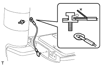 |
Install the tail gate cable and gate side shaft to the tail gate.
Install the tail gate cable and deck side shaft to the body.
| 7. INSTALL SIDE GATE SUPPORT SUB-ASSEMBLY LH |
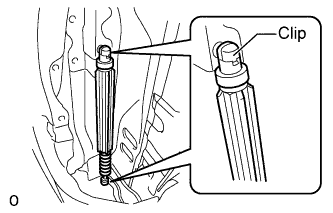 |
Install the side gate support.
| 8. INSTALL REAR COMBINATION LIGHT ASSEMBLY LH |
Put protective tape around the rear combination light assembly LH.
Connect each connector.
Attach the 2 clips to install the rear combination light assembly LH.
Using a T30 "TORX" socket wrench, install the 2 screws.
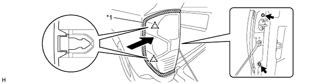
| *1 | Protective Tape | - | - |
| 9. INSTALL TAIL GATE LOCK STRIKER |
Using a T40 "TORX" wrench, install the 2 tail gate lock strikers with the 4 screws.
| 10. INSTALL TAIL GATE LOCK KEY CYLINDER |
Install the tail gate lock cylinder with the snap ring.
| 11. INSTALL TAIL GATE HANDLE ASSEMBLY |
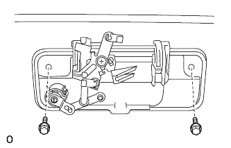 |
Install the tail gate handle with the 2 bolts.
| 12. INSTALL TELEVISION CAMERA ASSEMBLY (w/ Rear View Monitor System) |
Install the television camera assembly with the 2 bolts.
Connect the television camera connector.
| 13. INSTALL TAIL GATE LOCK CONTROL LINK LH |
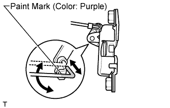 |
Install the control rod.
| 14. INSTALL TAIL GATE LOCK CONTROL LINK RH |
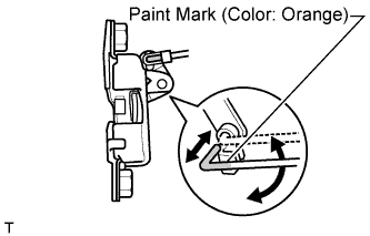 |
Install the control rod.
| 15. INSTALL TAIL GATE LOCK ASSEMBLY LH |
Using a T40 "TORX" wrench, install the tail gate lock with the 2 screws.
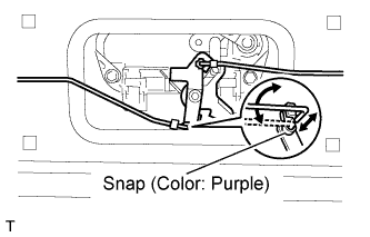 |
Connect one end of the tail gate lock link to the tail gate lock and another end to the tail gate handle.
| 16. INSTALL TAIL GATE LOCK ASSEMBLY RH |
Using a T40 "TORX" wrench, install the tail gate lock with the 2 screws.
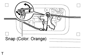 |
Connect one end of the tail gate lock link to the tail gate lock and another end to the tail gate handle.
| 17. INSTALL TAIL GATE SERVICE HOLE COVER |
Using a T30 "TORX" wrench, install the service hole cover with the 8 screws.
| 18. INSTALL TAIL GATE PROTECTOR |
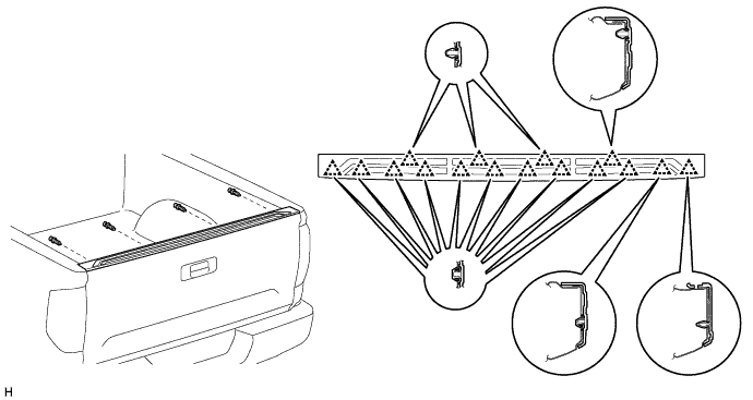
Attach the 16 clips to install the tail gate protector.
Install the 4 clips.
| 19. CHECK CONNECTION OF TELEVISION CAMERA ASSEMBLY (w/ Rear View Monitor System) |
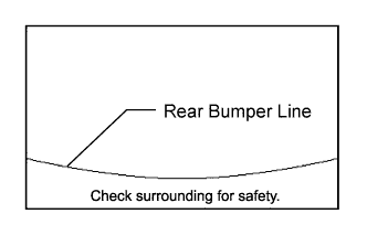 |
Move the shift lever to R and check that the rear view image in the display has no lines or distortion and has good color.