 |
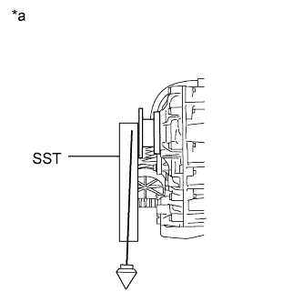
Using SST, measure and record the angle of the transfer flange (A).
- SST
- 09370-50010
| *a | Transfer Flange Angle: A |
PROPELLER SHAFT ASSEMBLY (for 4WD) > INSTALLATION |
| 1. MEASURE TRANSFER AND DIFFERENTIAL FLANGE ANGLE |
|
Using SST, measure and record the angle of the transfer flange (A).
| *a | Transfer Flange Angle: A |
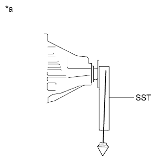 |
Using SST, measure and record the angle of the rear differential flange (B).
| *a | Rear Differential Flange Angle: B |
| 2. TEMPORARILY INSTALL PROPELLER WITH CENTER BEARING SHAFT ASSEMBLY |
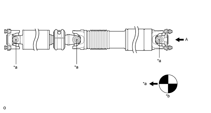
| *a | Grease Fitting | *b | View A |
 | A | - | - |
Completely remove any oil or the like and clean the contact surfaces of the propeller shaft flange, transfer flange and differential flange.
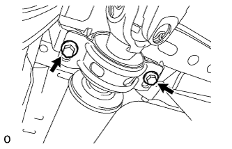 |
w/o Bearing Washer:
Temporarily install the center support bearing to the crossmember with the 2 mounting bolts.
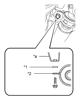 |
w/ Bearing Washer:
Temporarily install the center support bearing to the crossmember with the 2 bearing washers and 2 mounting bolts.
| *1 | No. 2 Center Support Bearing Washer |
| *2 | No. 1 Center Support Bearing Assembly |
| *a | Frame |
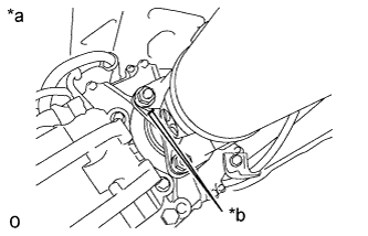 |
Align the matchmarks on the flange yoke and transfer flange.
| *a | for Transfer Side |
| *b | Matchmark |
Install the propeller shaft to the transfer side with the 4 nuts.
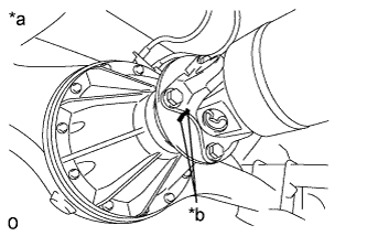 |
Align the matchmarks on the flange yoke and differential flange.
| *a | for Differential Side |
| *b | Matchmark |
Install the propeller shaft to the differential side with the 4 bolts and 4 nuts.
| 3. TIGHTEN PROPELLER WITH CENTER BEARING SHAFT ASSEMBLY |
With the vehicle empty and all 4 tires supported by a lift, or with the vehicle suspension in the full rebound position, adjust the center bearing so that dimension A (the distance from the front surface of the center bearing housing to the back surface of the intermediate shaft) is as shown in the chart below.
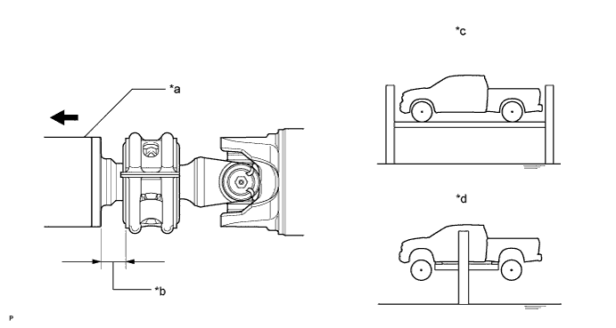
| Vehicle model | Vehicle condition | Dimension A |
| All model | Tires supported and vehicle empty (When using drive-on type lift) | 26.0 mm (1.024 in.) |
| Full rebound position (When using 2 post lift) | 26.0 mm (1.024 in.) |
| *a | Intermediate Shaft | *b | Dimension A |
| *c | Tires supported and vehicle empty (When using driveon type lift) | *d | Full rebound position (When using 2 post lift) |
| Front Side | - | - |
Check that the center line of the bracket is at right angles to the shaft axial direction.
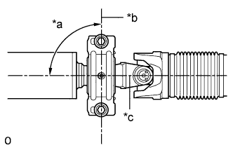 |
Tighten the 2 mounting bolts.
| *a | 90° |
| *b | Bracket Center Line |
| *c | Shaft Axial Direction |
| 4. INSPECT PROPELLER SHAFT JOINT ANGLE |
Measure the No. 1 joint angle.
Using SST, measure and record the angle of the intermediate shaft (C).
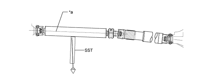
| *a | Intermediate Shaft Angle: C | - | - |
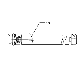 |
Subtract the angle of the transfer flange (A) measured before installing the propeller shaft from the angle of the intermediate shaft (C) to calculate the No. 1 joint angle.
| Intermediate Shaft Angle Measured Value (C) | transfer Flange Angle Measured Value (A) | No. 1 Joint Angle (Calculated Value) (C) - (A) |
| 2°30' (2.50°) | 3°45' (3.75°) | -1°15' (-1.25°) |
| *a | No. 1 Joint Angle |
| Vehicle model | No. 1 joint angle |
| USK56L-CRTSKA USK56L-CRTLKA | 0°52' +/-0°60' (0.87° +/-1.00°) |
| USK56L-CRTSKA* USK56L-CRTLKA* | 0°52' +/-0°60' (0.87° +/-1.00°) |
| USK56L-CRTSGA USK56L-CRTLGA | 0°52' +/-0°60' (0.87° +/-1.00°) |
| USK56L-CRTSGA* USK56L-CRTLGA* | 0°52' +/-0°60' (0.87° +/-1.00°) |
| USK57L-CHTSKA USK57L-CHTSGA | 1°07' +/-0°60' (1.12° +/-1.00°) |
| USK57L-CHTSKA* USK57L-CHTSGA* | 1°07' +/-0°60' (1.12° +/-1.00°) |
| USK56L-PSTSKA USK56L-PSTLKA | 0°52' +/-0°60' (0.87° +/-1.00°) |
| USK56L-PSTSKA* USK56L-PSTLKA* | 0°52' +/-0°60' (0.87° +/-1.00°) |
| USK56L-PSTSGA USK56L-PSTLGA | 0°52' +/-0°60' (0.87° +/-1.00°) |
| USK56L-PSTSGA* USK56L-PSTLGA* | 0°52' +/-0°60' (0.87° +/-1.00°) |
| UPK56L-CRTSKA UPK56L-CRTSKA* | 0°52' +/-0°60' (0.87° +/-1.00°) |
| UPK56L-PSTSKA UPK56L-PSTSKA* | 0°52' +/-0°60' (0.87° +/-1.00°) |
| USK56L-PSTZGA USK56L-PSTZKA | 0°52' +/-0°60' (0.87° +/-1.00°) |
| USK56L-PSTZGA* USK56L-PSTZKA* | 0°52' +/-0°60' (0.87° +/-1.00°) |
| USK56L-THTSGA USK56L-THTSKA | 0°52' +/-0°60' (0.87° +/-1.00°) |
| USK56L-THTSGA* USK56L-THTSKA* | 0°52' +/-0°60' (0.87° +/-1.00°) |
Measure the No. 2 joint angle.
Using SST, measure and record the angle of the propeller shaft (D).
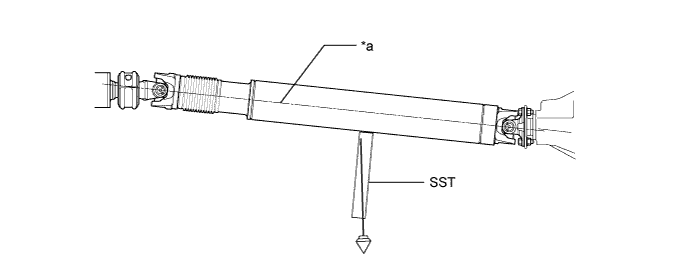
| *a | Propeller Shaft Angle: D | - | - |
Subtract the angle of the propeller shaft (D) from the angle of the intermediate shaft (C) to calculate the No. 2 joint angle.
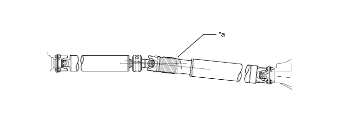
| Intermediate Shaft Angle Measured Value (C) | Propeller Shaft Angle Measured Value (D) | No. 2 Joint Angle (Calculated Value) (C) - (D) |
| 2°30' (2.50°) | 5°45' (5.75°) | -3°15' (-3.25°) |
| *a | No. 2 Joint Angle | - | - |
| Vehicle model | No. 2 joint angle |
| USK56L-CRTSKA USK56L-CRTLKA | -2°23' +/-0°60' (-2.38° +/-1.00°) |
| USK56L-CRTSKA* USK56L-CRTLKA* | -2°29' +/-0°60' (-2.48° +/-1.00°) |
| USK56L-CRTSGA USK56L-CRTLGA | -2°23' +/-0°60' (-2.38° +/-1.00°) |
| USK56L-CRTSGA* USK56L-CRTLGA* | -2°29' +/-0°60' (-2.48° +/-1.00°) |
| USK57L-CHTSKA USK57L-CHTSGA | -1°39' +/-0°60' (-1.65° +/-1.00°) |
| USK57L-CHTSKA* USK57L-CHTSGA* | -1°30' +/-0°60' (-1.50° +/-1.00°) |
| USK56L-PSTSKA USK56L-PSTLKA | -2°32' +/-0°60' (-2.53° +/-1.00°) |
| USK56L-PSTSKA* USK56L-PSTLKA* | -2°29' +/-0°60' (-2.48° +/-1.00°) |
| USK56L-PSTSGA USK56L-PSTLGA | -2°32' +/-0°60' (-2.53° +/-1.00°) |
| USK56L-PSTSGA* USK56L-PSTLGA* | -2°29' +/-0°60' (-2.48° +/-1.00°) |
| UPK56L-CRTSKA | -2°44' +/-0°60' (-2.73° +/-1.00°) |
| UPK56L-CRTSKA* | -2°26' +/-0°60' (-2.43° +/-1.00°) |
| UPK56L-PSTSKA | -2°19' +/-0°60' (-2.32° +/-1.00°) |
| UPK56L-PSTSKA* | -2°35' +/-0°60' (-2.58° +/-1.00°) |
| USK56L-PSTZGA USK56L-PSTZKA | -2°33' +/-0°60' (-2.55° +/-1.00°) |
| USK56L-PSTZGA* USK56L-PSTZKA* | -2°29' +/-0°60' (-2.49° +/-1.00°) |
| USK56L-THTSGA USK56L-THTSKA | -3°34' +/-0°60' (-3.57° +/-1.00°) |
| USK56L-THTSGA* USK56L-THTSKA* | -2°19' +/-0°60' (-2.32° +/-1.00°) |
Measure the No. 3 joint angle.
Subtract the angle of the rear differential flange (B) measured before installing the propeller shaft from the angle of the propeller shaft (D) to calculate the No. 3 joint angle.
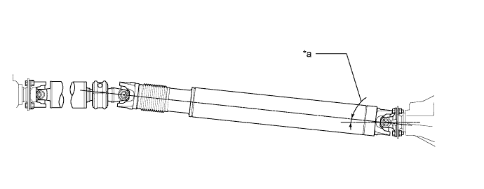
| Propeller Shaft Angle Measured Value (D) | Rear Differential Flange Angle Measured Value (B) | No. 3 Joint Angle (Calculated Value) (D) - (B) |
| 5°45' (5.75°) | 2°30' (2.50°) | 3°15' (3.25°) |
| *a | No. 3 Joint Angle | - | - |
| Vehicle model | No. 3 joint angle |
| USK56L-CRTSKA USK56L-CRTLKA | 2°59' +/-0°60' (2.98° +/-1.00°) |
| USK56L-CRTSKA* USK56L-CRTLKA* | 3°05' +/-0°60' (3.08° +/-1.00°) |
| USK56L-CRTSGA USK56L-CRTLGA | 2°59' +/-0°60' (2.98° +/-1.00°) |
| USK56L-CRTSGA* USK56L-CRTLGA* | 3°05' +/-0°60' (3.08° +/-1.00°) |
| USK57L-CHTSKA USK57L-CHTSGA | 3°29' +/-0°60' (3.48° +/-1.00°) |
| USK57L-CHTSKA* USK57L-CHTSGA* | 3°20' +/-0°60' (3.34° +/-1.00°) |
| USK56L-PSTSKA USK56L-PSTLKA | 3°38' +/-0°60' (3.63° +/-1.00°) |
| USK56L-PSTSKA* USK56L-PSTLKA* | 3°35' +/-0°60' (3.58° +/-1.00°) |
| USK56L-PSTSGA USK56L-PSTLGA | 3°38' +/-0°60' (3.63° +/-1.00°) |
| USK56L-PSTSGA* USK56L-PSTLGA* | 3°35' +/-0°60' (3.58° +/-1.00°) |
| UPK56L-CRTSKA | 3°49' +/-0°60' (3.82° +/-1.00°) |
| UPK56L-CRTSKA* | 3°31' +/-0°60' (3.52° +/-1.00°) |
| UPK56L-PSTSKA | 3°55' +/-0°60' (3.92° +/-1.00°) |
| UPK56L-PSTSKA* | 3°41' +/-0°60' (3.68° +/-1.00°) |
| USK56L-PSTZGA USK56L-PSTZKA | 3°38' +/-0°60' (3.64° +/-1.00°) |
| USK56L-PSTZGA* USK56L-PSTZKA* | 3°35' +/-0°60' (3.58° +/-1.00°) |
| USK56L-THTSGA USK56L-THTSKA | 4°36' +/-0°60' (4.61° +/-1.00°) |
| USK56L-THTSGA* USK56L-THTSKA* | 2°54' +/-0°60' (2.91° +/-1.00°) |
| 5. ADJUST PROPELLER SHAFT ANGLE |
Adjust the No. 1, No. 2 and No. 3 joint angle.
Support the propeller shaft with a jack.
Remove the 2 center bearing mounting bolts.
Slowly lower the jack, and disconnect the center bearing.
Select an appropriate center support bearing washer thickness from the table below, and obtain a washer set.
| Thickness |
| 2.0 mm (0.0787 in.) |
| 4.5 mm (0.1772 in.) |
| 6.5 mm (0.2559 in.) |
| 9.0 mm (0.3543 in.) |
| 11.0 mm (0.4331 in.) |
| 13.5 mm (0.5315 in.) |