Home › DRIVE LINE › PROPELLER SHAFT › PROPELLER SHAFT ASSEMBLY (for 4WD)

PROPELLER SHAFT ASSEMBLY (for 4WD) > INSPECTION

for Preparation Click here


1. INSPECT PROPELLER SHAFT WITH CENTER BEARING ASSEMBLY


C160096
  1. Using a dial indicator, measure the intermediate shaft runout.
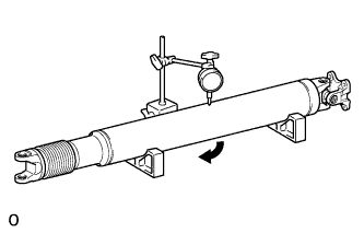
    Maximum runout:
    0.61 mm (0.0240 in.)

    1. If the intermediate shaft runout is more than the maximum, replace the propeller shaft with center bearing assembly.


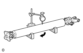
    C160097
  1. Using a dial indicator, measure the propeller shaft runout.

    Maximum runout:
    1.02 mm (0.0402 in.)

    1. If the propeller shaft runout is more than the maximum, replace the propeller shaft with center bearing assembly.


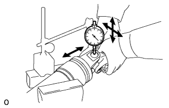
2. INSPECT REAR PROPELLER SHAFT UNIVERSAL JOINT SPIDER BEARING


C158513
  1. Mount the propeller shaft in a vise.

    NOTICE:
    Be careful not to grip the propeller shaft tube too tightly in a vise as this will cause deformation.

  1. Inspect the spider bearing for wear or damage.

  1. Using a dial indicator, measure the spider bearing axial play by turning the yoke of the flange while holding the shaft tightly.

    Maximum runout:
    0.05 mm (0.00197 in.)

    1. If the spider bearing axial play is more than the maximum, replace the spider bearing.


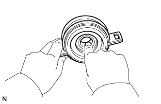
3. INSPECT NO. 1 CENTER SUPPORT BEARING ASSEMBLY


C134367
  1. Check that the bearing turns freely.

    1. If the bearing is damaged, worn, or does not turn freely, replace it.