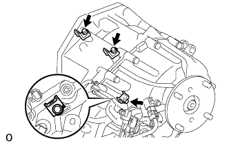
Home › DRIVE LINE › WF1AM TRANSFER › TRANSFER ASSEMBLY

TRANSFER ASSEMBLY > REASSEMBLY

for Preparation Click here


HINT:
Coat all of the sliding and rotating surfaces with Toyota Genuine Transfer gear oil LF 75W or equivalent before reassembly.


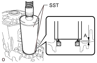
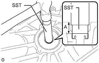
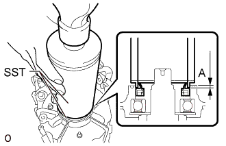
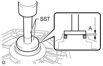
1. INSTALL TRANSFER CASE OIL SEAL


    C291178E01
  1. Using SST and a hammer, tap in a new transfer case oil seal as shown in the illustration.

    SST
    09950-60010   (09951-00630)
    09950-70010   (09951-07100)

    Drive in depth (A):
    1.4 to 2.4 mm (0.056 to 0.094 in.)

    NOTICE:
    Be careful not to damage or deform the transfer case oil seal.
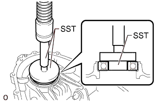


2. INSTALL TRANSFER DRIVEN SPROCKET BEARING (FRONT)


    C291180E01
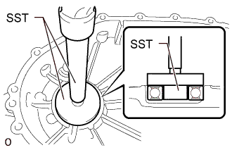
  1. Using SST and a press, press in a new transfer driven sprocket bearing (front) as shown in the illustration.

    SST
    09950-60010   (09951-00390, 09952-06010)
    09950-60020   (09951-00910)
    09950-70010   (09951-07100)

    NOTICE:
    The transfer driven sprocket bearing (front) should be installed completely.


3. INSTALL NO. 2 TRANSFER CASE OIL SEAL


    C291179E01
  1. Using SST and a press, press in a new No. 2 transfer case oil seal as shown in the illustration.

    SST
    09316-12010  
    09513-36040  

    Drive in depth (A):
    1.5 to 2.5 mm (0.060 to 0.098 in.)

    NOTICE:
    Be careful not to damage or deform the No. 2 transfer case oil seal.


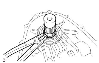
4. INSTALL OUTPUT SHAFT COMPANION FLANGE SUB-ASSEMBLY (FRONT)


    C291170
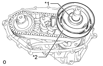
  1. Install the output shaft companion flange sub-assembly (front).

  1. Using a snap ring expander, install the shaft snap ring.


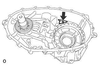
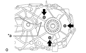
5. INSTALL TRANSFER OIL SEPARATOR


    C291201
  1. Using a T25 ''TORX'' socket wrench, install the bolt and transfer oil separator.

    Torque:
    7.6 N*m{ 77 kgf*cm , 67 in.*lbf }


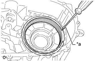
6. INSPECT TRANSFER LOWER PLANETARY RING GEAR


    C291169E01
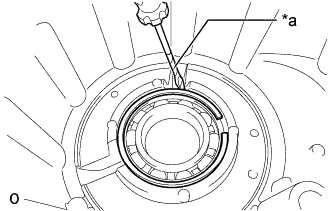
  1. Install the transfer lower planetary ring gear.

  1. Using a screwdriver, install the transfer lower planetary ring gear hole snap ring.
    Text in Illustration 
    *a
    Protective Tape

    HINT:
    Tape the screwdriver tip before use.


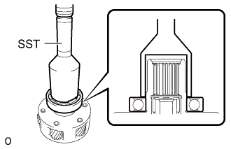
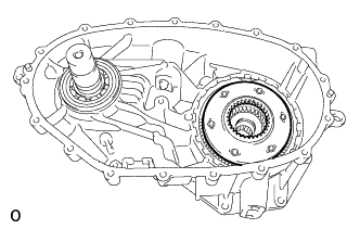
7. INSTALL TRANSFER LOWER PLANETARY GEAR ASSEMBLY


    C291181E01
  1. Using SST and a press, press in a new transfer input gear radial ball bearing.

    SST
    09214-76011  

    NOTICE:
    The transfer input gear radial ball bearing should be installed completely.


    C291167
  1. Install the transfer lower planetary gear assembly.


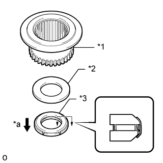
8. INSTALL TRANSFER HIGH AND LOW CLUTCH SLEEVE


    C291223E01
  1. Install the transfer lower planetary gear bearing, the No. 2 transfer output shaft spacer and the transfer high and low clutch sleeve.
    Text in Illustration 
    *1
    Transfer High and Low Clutch Sleeve
    *2
    No. 2 Transfer Output Shaft Spacer
    *3
    Transfer Lower Planetary Gear Bearing
    *a
    Transfer Lower Planetary Gear Assembly Side

    NOTICE:
    Make sure that the transfer lower planetary gear bearing is installed facing the correct direction.


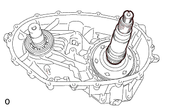
9. INSTALL REAR TRANSFER OUTPUT SHAFT


    C291165
  1. Install the rear transfer output shaft.


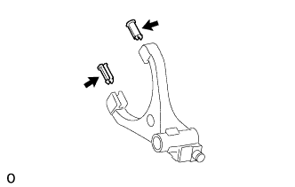
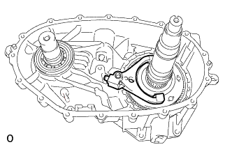
10. INSTALL NO. 1 TRANSFER GEAR SHIFT FORK


    C291207
  1. Install the 2 gear shift fork pads to the No. 1 transfer gear shift fork.


    C291164
  1. Install the No. 1 transfer gear shift fork.


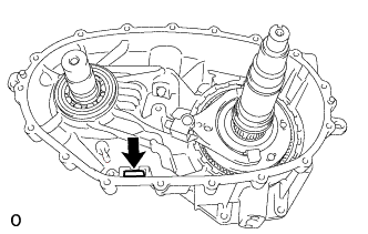
11. INSTALL TRANSFER CASE MAGNET


    C291163
  1. Install the transfer case magnet.


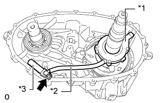
12. INSTALL TRANSFER OIL PUMP BODY SUB-ASSEMBLY


    C291162E01
  1. Install the transfer oil strainer sub-assembly to the transfer oil tube.

  1. Install the transfer oil tube to the transfer oil pump body sub-assembly.

  1. Install the transfer oil pump body sub-assembly together with the transfer oil tube and transfer oil strainer sub-assembly.
    Text in Illustration 
    *1
    Transfer Oil Pump Body Sub-assembly
    *2
    Transfer Oil Tube
    *3
    Transfer Oil Strainer Sub-assembly

  1. Using a T25 ''TORX'' socket wrench, install the bolt.

    Torque:
    7.6 N*m{ 77 kgf*cm , 67 in.*lbf }


13. INSTALL TRANSFER DRIVE SPROCKET SUB-ASSEMBLY


    C291161
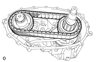
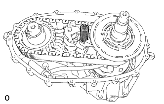
  1. Install the transfer drive sprocket sub-assembly and transfer driven sprocket to the front transfer drive chain.

  1. Install the transfer drive sprocket sub-assembly together with the front transfer drive chain and transfer driven sprocket.

    NOTICE:
    Do not drop the transfer drive sprocket sub-assembly, front transfer drive chain and transfer driven sprocket.


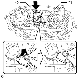
14. INSTALL CONTROL SELECT SHAFT SUB-ASSEMBLY


  1. Install the control select shaft sub-assembly.

    NOTICE:
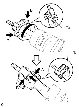
    When removing the rear transfer case, the spring of the control select shaft sub-assembly may become detached. Check the condition of the spring before installing the control select shaft sub-assembly, and if the spring is not in the correct position, correct the spring as shown in the illustration.

    CAUTION:
    1. Wear protective gloves to avoid injuries to your hands.
    2. Take care when performing this procedure as the spring is under high tension.


      C291189E01
    1. Make sure the spring is positioned as indicated by arrows A and B, and then rotate the control select shaft in the direction indicated by the arrow shown in the illustration.

    2. Rotate the control select shaft until the part of the spring indicated by arrow A moves past the part indicated by arrow B.

    3. Slide the control select shaft in the direction indicated by arrow C in the illustration to return the spring to the correct position.
      Text in Illustration 
      *a
      Part of the Spring Shown by Arrow A in the Open Position
      *b
      Control Select Shaft Sub-assembly in Correct Position


    C291214E01
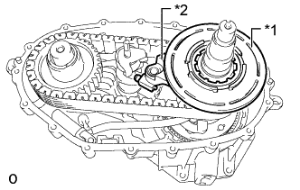
  1. Install the No. 1 transfer gear shift fork to the side of the control select shaft sub-assembly as shown in the illustration.
    Text in Illustration 
    *1
    No. 1 Transfer Gear Shift Fork
    *2
    Control Select Shaft Sub-assembly


15. INSTALL SOLENOID LOCK PLATE WITH NO. 2 TRANSFER GEAR SHIFT FORK


    C291158E01
  1. Install the No. 2 transfer gear shift fork to the solenoid lock plate.

  1. Install the solenoid lock plate together with the No. 2 transfer gear shift fork.
    Text in Illustration 
    *1
    Solenoid Lock Plate Assembly
    *2
    No. 2 Transfer Gear Shift Fork Sub-assembly


16. INSTALL TRANSFER HIGH AND LOW SHIFT FORK SHAFT


    C291215
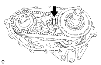
  1. Install the transfer high and low shift fork shaft.


17. INSTALL TRANSFER SELECT RETURN SPRING


    C291156
  1. Install the transfer select return spring.


18. INSTALL SOLENOID COVER


    C291155E01
  1. Install the solenoid cover and No. 1 transfer output shaft spacer.
    Text in Illustration 
    *1
    No. 1 Transfer Output Shaft Spacer
    *2
    Solenoid Cover


19. INSTALL REAR TRANSFER OUTPUT SHAFT RADIAL BALL BEARING


    C291154E01
  1. Install the rear transfer output shaft radial ball bearing.

  1. Using a screwdriver, install the transfer output shaft rear shaft snap ring.
    Text in Illustration 
    *a
    Protective Tape

    HINT:
    Tape the screwdriver tip before use.


20. INSTALL TRANSFER DRIVEN SPROCKET BEARING (REAR)


    C291182E01
  1. Using SST and a hammer, tap in a new transfer driven sprocket bearing (rear).

    SST
    09950-60010   (09951-00340, 09952-06010)
    09950-60020   (09951-00730)
    09950-70010   (09951-07150)

    NOTICE:
    The transfer driven sprocket bearing (rear) should be installed completely.


21. INSTALL TRANSFER COVER TYPE T OIL SEAL


    C291216E01
  1. Using SST and a hammer, tap in a new transfer cover type T oil seal.
    SST
    09950-70010   (09951-07100)
    09950-60010   (09951-00190)

    Drive in depth (A):
    14.4 to 15.4 mm (0.567 to 0.606 in.)


22. INSTALL SOLENOID COIL SUB-ASSEMBLY


    C291151E01
  1. Install the solenoid coil sub-assembly with the 3 nuts.

    Torque:
    9.5 N*m{ 97 kgf*cm , 84 in.*lbf }

    Text in Illustration 
    *a
    Rear Transfer Case Hole

    HINT:
    Make sure that the solenoid coil sub-assembly terminal extends out from the rear transfer case hole.

  1. Connect the solenoid coil sub-assembly terminal.


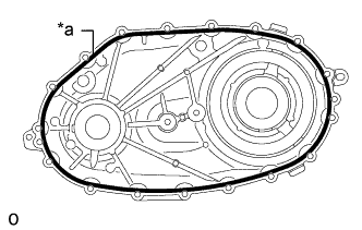
23. INSTALL REAR TRANSFER CASE


    C291212E01
  1. Apply seal packing to the rear transfer case as shown in the illustration.

    Seal packing:
    Toyota Genuine Seal Packing 1281, Three Bond 1281 or equivalent

    Text in Illustration 
    *a
    Seal Packing

    NOTICE:
    If the removed rear transfer case will be reused: After removing the rear transfer case, be sure to perform the following before reinstalling it: 1) using a knife, cut off any old seal packing on the contact surface of the rear transfer case, 2) clean off any remaining old seal packing from the contact surface of the rear transfer case, and 3) reapply seal packing to the rear transfer case.


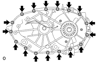
    C291150
  1. Using a 40 IP ''TORX PLUS'' socket wrench or T40 ''TORX'' socket wrench, install the 17 bolts.

    Torque:
    35 N*m{ 357 kgf*cm , 26 ft.*lbf }

    NOTICE:
    Tighten the bolts of the rear transfer case within 10 minutes of applying the seal packing. The seal packing will dry very quickly.


24. INSTALL TRANSFER INDICATOR SWITCH
  1. Using SST, install the transfer indicator switch.

    SST
    09224-00010  

    Torque:
    41 N*m{ 413 kgf*cm , 30 ft.*lbf }

    NOTICE:
    Use the formula below to calculate special torque values for situations where SST is combined with a torque wrench (Click here).

  1. Connect the connector and attach the clamp.


25. INSTALL TRANSFER OUTPUT SHAFT TYPE T OIL SEAL
  1. Apply Toyota Genuine Transfer gear oil LF 75W or equivalent to the spline area of the rear transfer output shaft.


    C291185E01
  1. Using SST and a hammer, tap in a new transfer output shaft type T oil seal as shown in the illustration.

    SST
    09502-12010  
    09513-36040  

    Drive in depth (A):
    1.4 to 2.4 mm (0.056 to 0.094 in.)


26. INSTALL OUTPUT SHAFT COMPANION FLANGE SUB-ASSEMBLY (REAR)
  1. Install the output shaft companion flange sub-assembly (rear) onto the rear transfer output shaft.


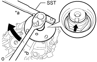
    C291217E01
  1. Using SST, hold the output shaft companion flange sub-assembly (rear).

    SST
    09330-00021  

  1. Using a 30 mm socket wrench, install a new O-ring and a new transfer output shaft nut.

    Torque:
    127 N*m{ 1295 kgf*cm , 94 ft.*lbf }

    Text in Illustration 
    *a
    Hold
    *b
    Turn


    F050151E05
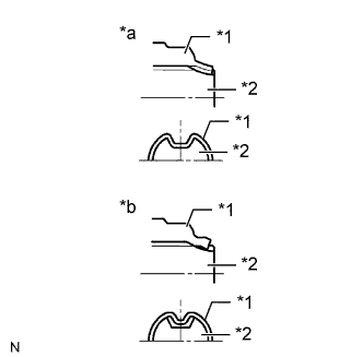
  1. Using a chisel and hammer, stake the transfer output shaft nut.
    Text in Illustration 
    *1
    Transfer Output Shaft Nut
    *2
    Rear Transfer Output Shaft
    *a
    Correct
    *b
    Incorrect


27. INSTALL TRANSFER SHIFT ACTUATOR ASSEMBLY


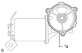
    C291221E01
  1. Apply seal packing to the transfer shift actuator assembly as shown in the illustration.

    Seal packing:
    Toyota Genuine Seal Packing 1281, Three Bond 1281 or equivalent

    Text in Illustration 
    *a
    Seal Packing

    NOTICE:
    If the removed transfer shift actuator assembly will be reused: After removing the transfer shift actuator assembly, be sure to perform the following before reinstalling it: 1) using a knife, cut off any old seal packing on the contact surface of the transfer shift actuator assembly, 2) clean off any remaining old seal packing from the contact surface of the transfer shift actuator assembly, and 3) reapply seal packing to the transfer shift actuator assembly.

  1. Install the transfer shift actuator assembly with the 4 bolts.

    Torque:
    9.5 N*m{ 97 kgf*cm , 84 in.*lbf }

    NOTICE:
    Tighten the bolts of the transfer shift actuator assembly within 10 minutes of applying the seal packing. The seal packing will dry very quickly.

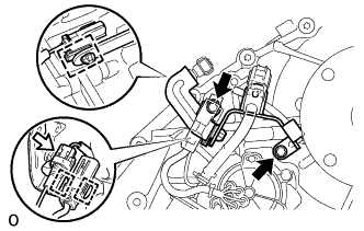
  1. Connect the 3 connectors and attach the 2 clamps.


28. INSTALL WIRING HARNESS CLAMP BRACKET


    C291143
  1. Install the wiring harness clamp bracket with the 2 bolts.

    Torque:
    9.5 N*m{ 97 kgf*cm , 84 in.*lbf }

  1. Connect the connector and 3 clamps.


    C291200
  1. Install the 3 wiring harness clamp brackets with the 3 bolts.

    Torque:
    8.0 N*m{ 82 kgf*cm , 71 in.*lbf }

    NOTICE:
    Install the wiring harness clamp bracket in the correct direction.


29. INSTALL LOWER TRANSFER CASE PROTECTOR
  1. Install the lower transfer case protector with the 4 bolts.

    Torque:
    22 N*m{ 219 kgf*cm , 16 ft.*lbf }