Install the 2 bolts <G>.
- Torque:
- 20 N*m{ 204 kgf*cm , 15 ft.*lbf }
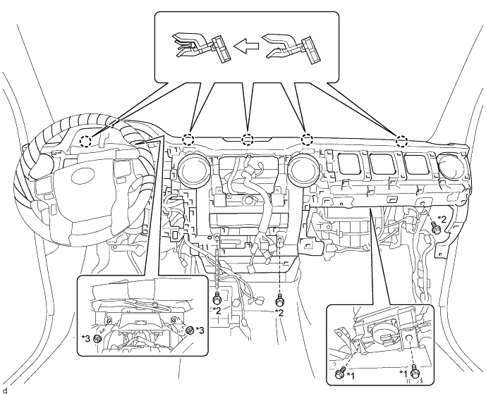
| *1 | Bolt <G> | *2 | Bolt <B> |
| *3 | Nut <C> | - | - |
INSTRUMENT PANEL SAFETY PAD (for Floor Shift Type) > INSTALLATION |
| 1. INSTALL NO. 1 INSTRUMENT PANEL CLIP |
Attach the 2 claws to install the 2 No. 1 instrument panel clips.
| 2. INSTALL NO. 3 INSTRUMENT PANEL STAY |
Attach the 3 claws to install the 3 No. 3 instrument panel stays.
| 3. INSTALL INSTRUMENT PANEL SUB-ASSEMBLY |
Set the instrument panel sub-assembly and attach the 5 claws.
Install the 2 nuts <C> and 3 bolts <B>.
Install the 2 bolts <G>.
| *1 | Bolt <G> | *2 | Bolt <B> |
| *3 | Nut <C> | - | - |
for Automatic Air Conditioning System:
Attach the 2 claws to connect the cooler thermistor.
Connect each connector and attach each wire harness clamp.
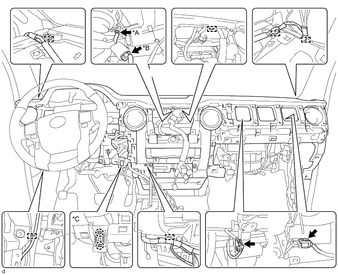
| *A | w/ Automatic Light Control System | *2 | w/ Front Center Speaker |
| *3 | for Automatic Air Conditioning System | - | - |
| 4. INSTALL FRONT NO. 2 SPEAKER ASSEMBLY LH |
Connect the connector.
Temporarily install the front No. 2 speaker assembly LH by aligning the positioning pins of the front No. 2 speaker assembly LH with the instrument panel.
Install the front No. 2 speaker assembly LH with the 2 bolts.
| 5. INSTALL INSTRUMENT PANEL SPEAKER PANEL SUB-ASSEMBLY |
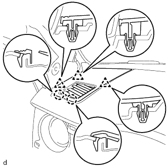 |
Attach the 3 clips and 2 claws to install the instrument panel speaker panel sub-assembly.
| 6. INSTALL FRONT NO. 2 SPEAKER ASSEMBLY RH |
Connect the connector.
Temporarily install the front No. 2 speaker assembly RH by aligning the positioning pins of the front No. 2 speaker assembly RH with the instrument panel.
Install the front No. 2 speaker assembly RH with the 2 bolts.
| 7. INSTALL NO. 2 INSTRUMENT PANEL SPEAKER PANEL SUB-ASSEMBLY |
| 8. INSTALL FRONT PILLAR GARNISH LH |
Attach the clip to install the front pillar garnish LH.
Install the bolt.
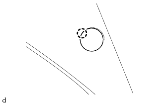 |
Attach the claw to close the cover.
| 9. INSTALL FRONT DOOR OPENING TRIM WEATHERSTRIP LH |
Install the front door opening trim weatherstrip LH.
| 10. INSTALL FRONT PILLAR GARNISH RH |
Attach the clip to install the front pillar garnish RH.
Install the front assist grip sub-assembly to the front pillar garnish RH with the 2 bolts.
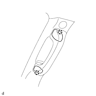 |
Attach the 2 claws to close the 2 assist grip covers.
| 11. INSTALL FRONT DOOR OPENING TRIM WEATHERSTRIP RH |
| 12. INSTALL CENTER INSTRUMENT CLUSTER FINISH PANEL SUB-ASSEMBLY |
for 4WD:
Connect the connector.
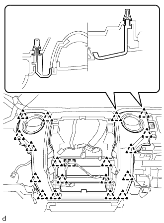 |
Attach the 18 clips and wire harness clamp to install the center instrument cluster finish panel sub-assembly.
| 13. INSTALL RADIO AND DISPLAY RECEIVER ASSEMBLY WITH BRACKET |
Connect each connector.
Insert the radio and display receiver assembly with bracket and attach the 2 guides and 3 clips on its backside.
Install the radio and display receiver assembly with bracket with the 4 bolts.
| 14. INSTALL LOWER CENTER INSTRUMENT PANEL FINISH PANEL WITH AIR CONDITIONING CONTROL ASSEMBLY |
Connect each connector.
Attach the 8 clips, 2 claws and guide to install the lower center instrument panel finish panel together with the air conditioning control assembly.
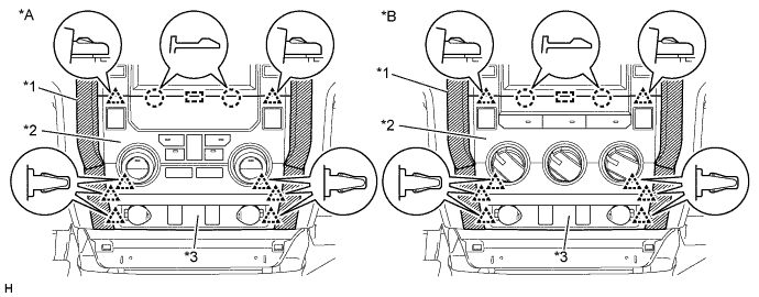
| *A | for Automatic Air Conditioning System | *B | for Manual Air Conditioning System |
| *1 | Protective Tape | *2 | Air Conditioning Control Assembly |
| *3 | Lower Center Instrument Panel Finish Panel | - | - |
| 15. INSTALL NO. 2 INSTRUMENT CLUSTER FINISH PANEL GARNISH |
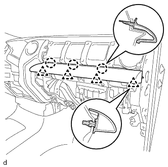 |
Attach the 3 claws and 4 clips to install the No. 2 instrument cluster finish panel garnish.
| 16. INSTALL LOWER INSTRUMENT PANEL FINISH PANEL SUB-ASSEMBLY RH |
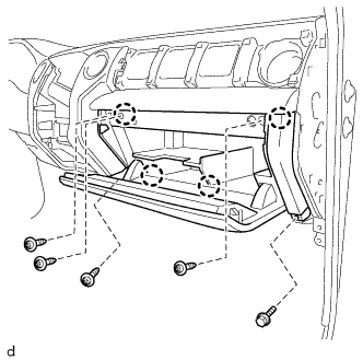 |
Attach the 4 claws to install the lower instrument panel finish panel sub-assembly RH.
Install the 4 screws <F> and bolt <A>.
| 17. INSTALL INSTRUMENT SIDE PANEL RH |
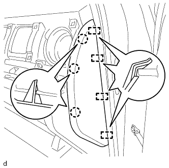 |
Attach the 4 guides and 3 claws to install the instrument side panel RH.
| 18. INSTALL NO. 4 INSTRUMENT REGISTER SUB-ASSEMBLY |
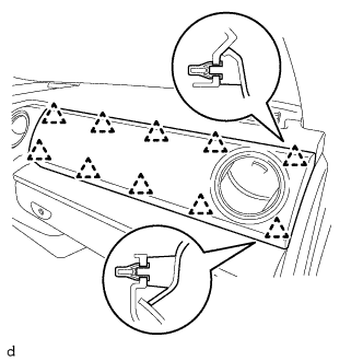 |
Attach the 10 clips to install the No. 4 instrument register sub-assembly.
| 19. INSTALL LOWER NO. 2 INSTRUMENT PANEL AIRBAG ASSEMBLY |
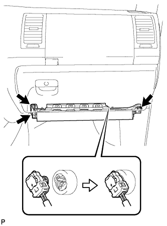 |
Connect the connector.
Install the 3 bolts to install the instrument panel airbag.
| 20. INSTALL LOWER INSTRUMENT PANEL |
Attach the 3 claws to install the lower instrument panel.
Install the bolt <A> and screw <D>.
| 21. INSTALL NO. 2 INSTRUMENT PANEL UNDER COVER SUB-ASSEMBLY |
Attach the 2 guides, 4 claws and clip to install the No. 2 instrument panel under cover sub-assembly.
| 22. INSTALL COMBINATION METER ASSEMBLY |
Pass the combination meter assembly between the steering wheel assembly and instrument panel.
Connect the connector and attach the wire harness clamp.
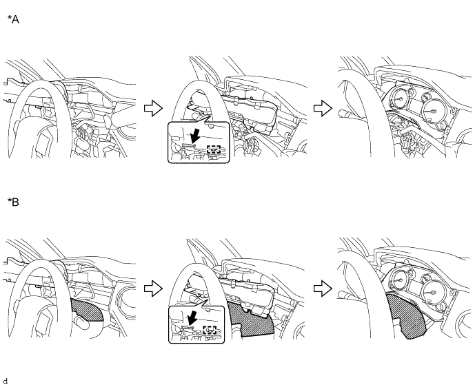
| *A | for Column Shift Type | *2 | for Floor Shift Type |
Install the combination meter assembly with the 4 screws.
| 23. INSTALL INSTRUMENT CLUSTER FINISH PANEL ASSEMBLY |
Attach the 6 clips to install the instrument cluster finish panel assembly.
Install the 2 clips.
| 24. INSTALL INSTRUMENT CLUSTER FINISH PANEL ORNAMENT |
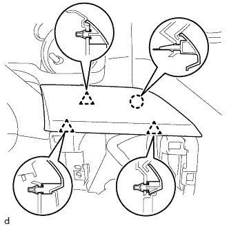 |
Attach the 3 clips and claw to install the instrument cluster finish panel ornament.
| 25. INSTALL NO. 2 SWITCH HOLE BASE |
Connect each connector.
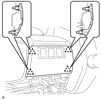 |
Attach the 4 clips to install the No. 2 switch hole base.
| 26. INSTALL NO. 1 INSTRUMENT CLUSTER FINISH PANEL GARNISH |
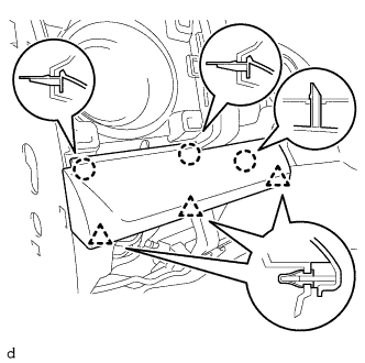 |
Attach the 3 clips and 3 claws to install the No. 1 instrument cluster finish panel garnish.
| 27. INSTALL LOWER NO. 1 INSTRUMENT PANEL AIRBAG ASSEMBLY |
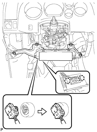 |
Connect the connector.
Attach the 2 claws to install the DLC3.
Install the 4 bolts to install the instrument panel airbag.
| 28. INSTALL LOWER INSTRUMENT PANEL FINISH PANEL SUB-ASSEMBLY LH |
Connect the hood lock control cable to the hood lock control lever, rotate the hood lock control cable, and then slide and push the hood lock control cable into place.
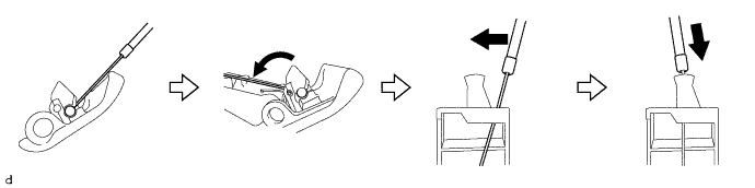
Attach the 3 hooks to connect the hood lock control lever to the lower instrument panel finish panel sub-assembly LH.
Connect each connector.
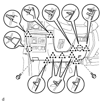 |
Attach the 9 clips and 2 claws to install the lower instrument panel finish panel sub-assembly LH.
Install the 2 bolts <A>.
| 29. INSTALL COWL SIDE TRIM BOARD LH |
Attach the 2 clips to install the cowl side trim board LH.
Install the nut.
| 30. INSTALL FRONT DOOR SCUFF PLATE LH |
Attach the 6 claws and 3 clips to install the front door scuff plate LH.
| 31. INSTALL COWL SIDE TRIM BOARD RH |
| 32. INSTALL FRONT DOOR SCUFF PLATE RH |
| 33. INSTALL FRONT CONSOLE BOX |
Install the front console box with the 5 screws <E>.
Install the 2 clips and attach the connector.
| 34. INSTALL REAR CONSOLE BOX ASSEMBLY |
Install the rear console box assembly with the 2 screws <E> and 4 bolts <B>.
Connect the 2 connectors.
| 35. INSTALL CONSOLE BOX CARPET |
Install the console box carpet.
| 36. INSTALL REAR CONSOLE END PANEL SUB-ASSEMBLY |
w/ Power Outlet Socket:
Attach the 2 wire harness clamps and connect the connector.
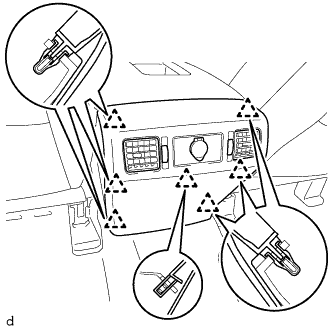 |
Attach the 7 clips to install the rear console end panel sub-assembly.
| 37. INSTALL UPPER CONSOLE PANEL SUB-ASSEMBLY |
Attach the 12 clips to install the upper console panel sub-assembly.
| 38. INSTALL UPPER REAR CONSOLE PANEL SUB-ASSEMBLY |
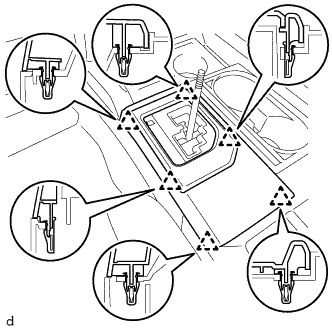 |
Attach the 6 clips to install the upper rear console panel sub-assembly.
| 39. INSTALL SHIFT LEVER KNOB SUB-ASSEMBLY |
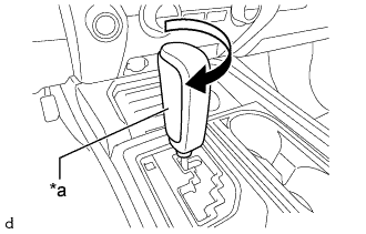 |
Twist the shift lever knob sub-assembly in the direction indicated by the arrow to install it.
| *a | Leather Portion |
| 40. INSTALL INSTRUMENT SIDE PANEL LH |
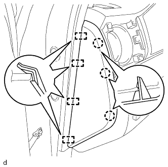 |
Attach the 4 guides and 3 claws to install the instrument side panel LH.
| 41. INSTALL NO. 1 INSTRUMENT PANEL REGISTER SUB-ASSEMBLY |
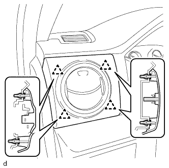 |
Attach the 4 clips to install the No. 1 instrument panel register sub-assembly.
| 42. CONNECT CABLE TO NEGATIVE BATTERY TERMINAL |
| 43. RESTORE AUTOAWAY/RETURN FUNCTION (for Power Tilt and Power Telescopic Steering Column) |
Restore the Autoaway/Return function setting to the previous condition by changing the customize parameter (Click here).
| 44. CHECK SRS WARNING LIGHT |