 |
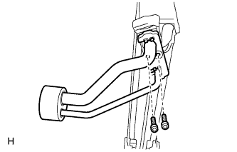
Sufficiently apply compressor oil to 4 new O-rings and the fitting surface of the hose joint.
- Compressor oil:
- ND-OIL 8 or equivalent
AIR CONDITIONING UNIT > REASSEMBLY |
| 1. INSTALL COOLER EXPANSION VALVE |
|
Sufficiently apply compressor oil to 4 new O-rings and the fitting surface of the hose joint.
Install the 2 O-rings to the No. 1 cooler evaporator sub-assembly.
Install the 2 O-rings to the tube and accessory.
Install the cooler expansion valve and tube and accessory to the No. 1 cooler evaporator sub-assembly.
Using a 4 mm hexagon wrench, install the 2 bolts.
| 2. INSTALL NO. 1 COOLER THERMISTOR |
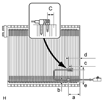 |
Install the No. 1 cooler thermistor to the No. 1 cooler evaporator sub-assembly as shown in the illustration.
| Area | Standard Dimension |
| a | 48 mm (1.89 in.) |
| b | 8.7 to 9.0 mm (0.343 to 0.354 in.) |
| c | 34.3 mm (1.35 in.) |
| d | 47.7 mm (1.88 in.) |
| e | 48 to 52 mm (1.89 to 2.04 in.) |
| 3. INSTALL NO. 1 COOLER EVAPORATOR SUB-ASSEMBLY |
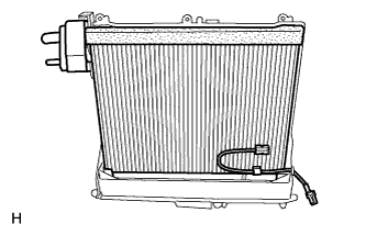 |
Install the No. 1 cooler evaporator sub-assembly to the blower case (front side).
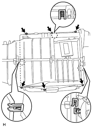 |
Install the blower case (back side).
Install the 6 screws and attach the 3 claws.
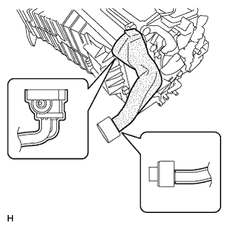 |
Install the No. 2 cooling unit packing and No. 1 cooling unit packing as shown in the illustration.
| 4. INSTALL HEATER RADIATOR UNIT SUB-ASSEMBLY |
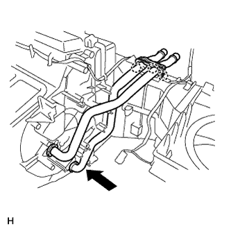 |
Install the heater radiator unit sub-assembly.
Attach the 3 claws to install the heater clamp.
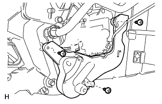 |
Install the plate with the 3 screws.
| 5. INSTALL COOLING UNIT DAMPER SERVO SUB-ASSEMBLY (for Automatic Air Conditioning System) |
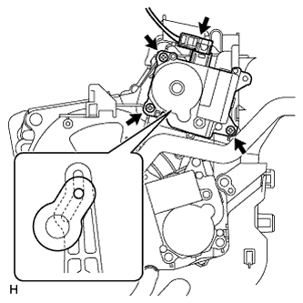 |
Install the cooling unit damper servo sub-assembly with the 3 screws as shown in the illustration.
Connect the connector.
| 6. INSTALL BLOWER DAMPER SERVO SUB-ASSEMBLY |
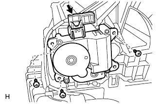 |
Install the blower damper servo sub-assembly with the 3 screws.
Connect the connector.
| 7. INSTALL BLOWER UPPER CASE SUB-ASSEMBLY |
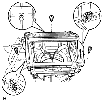 |
Attach the 2 claws to install the blower upper case sub-assembly.
Install the 3 screws.
| 8. INSTALL DAMPER SERVO SUB-ASSEMBLY (for Automatic Air Conditioning System) |
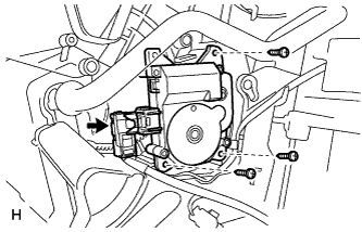 |
Install the damper servo sub-assembly with the 3 screws.
Connect the connector.
| 9. INSTALL NO. 1 DAMPER SERVO SUB-ASSEMBLY |
Set the No. 1 damper servo sub-assembly so that the cutout part engages with the tooth of the gear, and attach the claw to install the No. 1 damper servo sub-assembly.
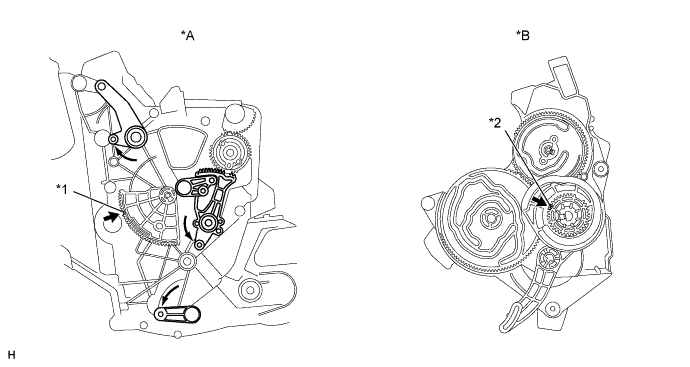
| *A | Air Conditioning Unit Side | *B | Damper Servo Side |
| *1 | Cutout | *2 | Tooth |
 | Rotate lever in direction of arrow until it stops | - | - |
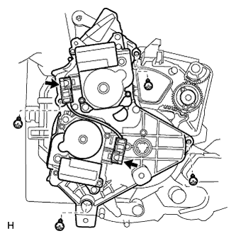 |
Install the 4 screws and connect the 2 connectors.
| 10. INSTALL AIR DUCT |
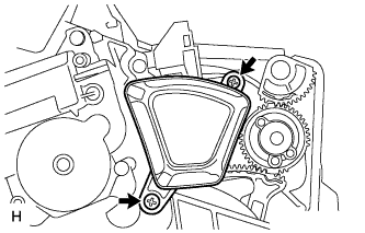 |
Install the air duct with the 2 screws.
| 11. INSTALL BLOWER WITH FAN MOTOR SUB-ASSEMBLY |
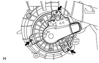 |
Install the blower with fan motor sub-assembly with the 3 screws.
| 12. INSTALL AIR CONDITIONING AMPLIFIER ASSEMBLY |
Install the air conditioning amplifier assembly with the 2 screws.
for Manual Air Conditioning System:
Connect the 2 connectors.
for Automatic Air Conditioning System:
Connect the 3 connectors.
| 13. INSTALL NO. 3 AIR DUCT SUB-ASSEMBLY |
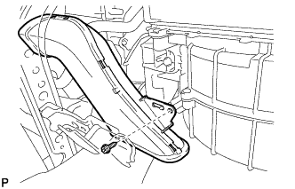 |
Install the No. 3 air duct sub-assembly with the screw.
| 14. INSTALL CLEAN AIR FILTER |
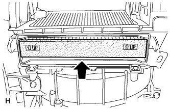 |
Install the clean air filter as shown in the illustration.
| 15. INSTALL AIR FILTER COVER PLATE |
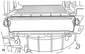 |
Attach the 2 claws to install the air filter cover plate.
| 16. INSTALL NO. 1 AIR DUCT SUB-ASSEMBLY |
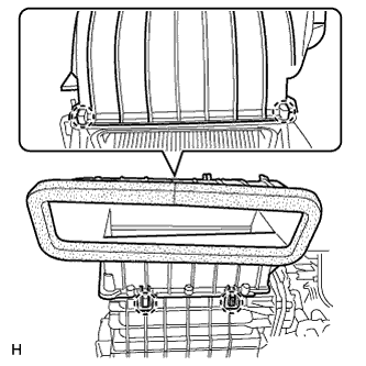 |
Attach the 4 claws to install the No. 1 air duct sub-assembly.
| 17. INSTALL LOWER DEFROSTER NOZZLE ASSEMBLY |
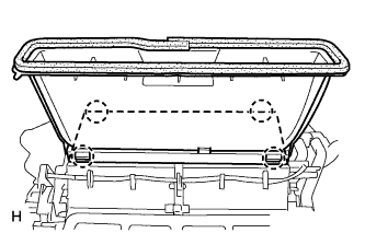 |
Attach the 4 claws to install the lower defroster nozzle assembly.