REAR BUMPER (for Resin Type Bumper) > REASSEMBLY |
| 1. INSTALL REAR BUMPER UPPER COVER LH |
Install the rear bumper upper cover LH with the 2 nuts.
| 2. INSTALL REAR BUMPER UPPER COVER RH |
| 3. INSTALL REAR BUMPER PLATE |
Install the rear bumper plate with the 2 bolts.
| 4. INSTALL REAR BUMPER SIDE STAY LH |
Install the rear bumper side stay LH with the 5 bolts.
| 5. INSTALL REAR BUMPER SIDE STAY RH |
| 6. INSTALL NO. 2 FRAME WIRE |
w/ Towing Package:
Attach all the clamps to install the No. 2 frame wire to the receiver hitch bracket sub-assembly.
w/o Towing Package:
Attach all the clamps to install the No. 2 frame wire to the rear bumper reinforcement sub-assembly.
| 7. INSTALL REAR BUMPER BAR CORNER REINFORCEMENT LH |
Install the rear bumper bar corner reinforcement LH with the 5 bolts.
| 8. INSTALL REAR BUMPER BAR CORNER REINFORCEMENT RH |
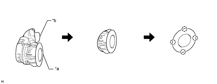
| 9. INSTALL NO. 3 ULTRASONIC SENSOR (w/ Intuitive Parking Assist System) |
Attach the 4 claws to install the No. 3 ultrasonic sensor as shown in the illustration.
| *a | No. 3 ultrasonic sensor direction |
| *b | Keyhole direction |
| 10. INSTALL NO. 2 ULTRASONIC SENSOR (w/ Intuitive Parking Assist System) |
Attach the 4 claws to install the No. 2 ultrasonic sensor as shown in the illustration.
| *a | No. 2 ultrasonic sensor direction |
| *b | Keyhole direction |
| 11. INSTALL BLIND SPOT MONITOR SENSOR LH (w/ Blind Spot Monitor System) |
Install the blind spot monitor sensor LH with the 3 nuts.
| 12. INSTALL BLIND SPOT MONITOR SENSOR RH (w/ Blind Spot Monitor System) |
| 13. INSTALL REAR BUMPER EXTENSION INSERT LH |
Install the rear bumper extension insert LH with the 8 clips.
| 14. INSTALL REAR BUMPER EXTENSION INSERT RH |
| 15. INSTALL LICENSE PLATE LIGHT ASSEMBLY LH |
Connect the connector.
Attach the 2 claws to install the license plate assembly LH.
| 16. INSTALL LICENSE PLATE LIGHT ASSEMBLY RH |
| 17. INSTALL REAR BUMPER PAD SUB-ASSEMBLY LH |
Attach the 12 claws and 2 guides to install the rear bumper pad sub-assembly LH.
Install the 3 clips.
| 18. INSTALL REAR BUMPER PLATE LH |
Attach the 3 claws and clip to install the rear bumper plate LH.
| 19. INSTALL REAR BUMPER PLATE RH |