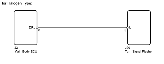
LIGHTING SYSTEM > DRL Relay Circuit |
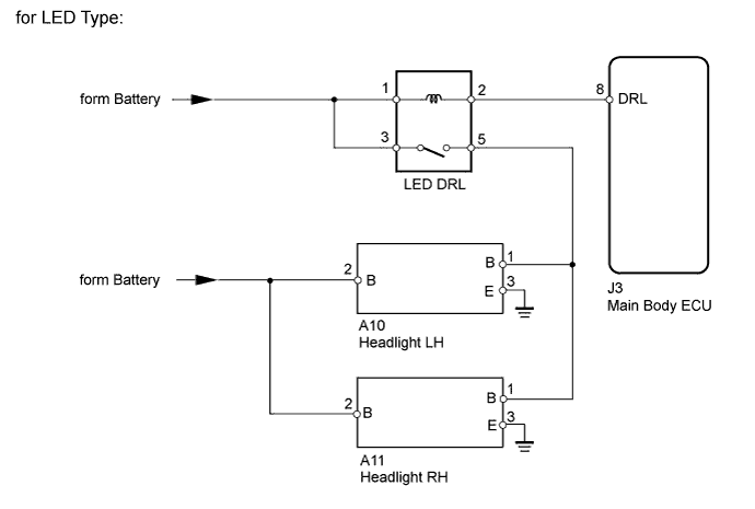
| 1.CHECK VEHICLE TYPE |
Check vehicle type.
| Result | Proceed to |
| for Halogen Type | A |
| for LED Type | B |
|
| ||||
| A | |
 |
| 2.CHECK HARNESS AND CONNECTOR (TURN SIGNAL FLASHER - MAIN BODY ECU) |
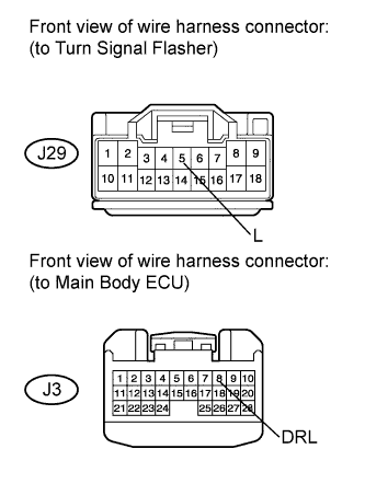 |
Disconnect the J29 relay connector.
Disconnect the J3 ECU connector.
Measure the resistance according to the value(s) in the table below.
| Tester Connection | Condition | Specified Condition |
| J29-5 (L) - J3-8 (DRL) | Always | Below 1 Ω |
| J29-5 (L) - Body ground | Always | 10 kΩ or higher |
|
| ||||
| OK | |
|
| 3.CHECK MAIN BODY ECU |
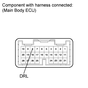 |
Disconnect the J29 relay connector.
Measure the voltage according to the value(s) in the table below.
| Tester Connection | Switch Condition | Specified Condition |
| 8 (DRL) - Body ground | Ignition switch ON | 11 to 14 V |
| Ignition switch OFF | Below 1 V |
|
| ||||
| OK | ||
 | ||
| ||
| 4.CHECK HARNESS AND CONNECTOR (HEADLIGHT - BATTERY) |
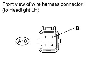 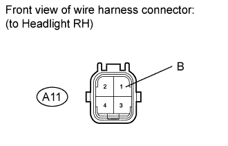 |
for LH:
Disconnect the A10 headlight connector.
Measure the voltage according to the value(s) in the table below.
| Tester Connection | Switch Condition | Specified Condition |
| A10-1 (B) - Body ground | Light control switch TAIL | 11 to 14 V |
| Light control switch except TAIL | Below 1 V |
for RH:
Disconnect the A11 headlight connector.
Measure the voltage according to the value(s) in the table below.
| Tester Connection | Switch Condition | Specified Condition |
| A11-1 (B) - Body ground | Light control switch TAIL | 11 to 14 V |
| Light control switch except TAIL | Below 1 V |
|
| ||||
| OK | ||
| ||
| ||
| 5.INSPECT DAYTIME RUNNING LIGHT RELAY (LED DRL) |
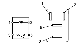 |
Remove the daytime running light relay from the engine room relay block.
Measure the resistance according to the value(s) in the table below.
| Tester Connection | Condition | Specified Condition |
| 3 - 5 | When battery voltage is applied to terminals 1 and 2 | Below 1 Ω |
| 3 - 5 | When battery voltage is not applied to terminals 1 and 2 | 10 kΩ or higher |
|
| ||||
| OK | |
|
| 6.CHECK HARNESS AND CONNECTOR (DAYTIME RUNNING LIGHT RELAY [LED DRL] - BATTERY) |
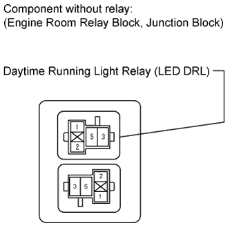 |
Remove the daytime running light relay from the engine room relay block.
Measure the voltage according to the value(s) in the table below.
| Tester Connection | Condition | Specified Condition |
| Daytime running light relay terminal 1 - Body ground | Always | 11 to 14 V |
| Daytime running light relay terminal 3 - Body ground |
|
| ||||
| OK | |
|
| 7.CHECK HARNESS AND CONNECTOR (DAYTIME RUNNING LIGHT RELAY [LED DRL] - HEADLIGHT) |
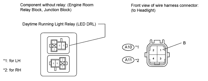
Remove the daytime running light relay from the engine room relay block.
Disconnect the A10*1 and A11*2 headlight connectors.
Measure the resistance according to the value(s) in the table below.
| Tester Connection | Condition | Specified Condition |
| Daytime running light relay terminal 5 - A10-1 (B)*1 | Always | Below 1 Ω |
| Daytime running light relay terminal 5 - Body ground*1 | Always | 10 kΩ or higher |
| Daytime running light relay terminal 5 - A11-1 (B)*2 | Always | Below 1 Ω |
| Daytime running light relay terminal 5 - Body ground*2 | Always | 10 kΩ or higher |
|
| ||||
| OK | |
|
| 8.CHECK HARNESS AND CONNECTOR (DAYTIME RUNNING LIGHT RELAY [LED DRL] - MAIN BODY ECU) |
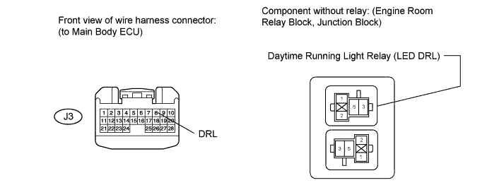
Remove the daytime running light relay from the engine room relay block.
Disconnect the J3 ECU connector.
Measure the resistance according to the value(s) in the table below.
| Tester Connection | Condition | Specified Condition |
| Daytime running light relay terminal 2 - J3-8 (DRL) | Always | Below 1 Ω |
| J3-8 (DRL) - Body ground | Always | 10 kΩ or higher |
|
| ||||
| OK | ||
| ||
| ||

