 |
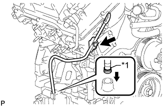
Install a new O-ring to the dipstick guide.
| *1 | New O-Ring |
ENGINE UNIT > INSTALLATION |
| 1. INSTALL FRONT NO. 1 ENGINE MOUNTING BRACKET RH |
Install the front No. 1 engine mounting bracket RH with the 4 bolts.
| 2. INSTALL FRONT NO. 1 ENGINE MOUNTING BRACKET LH |
Install the front No. 1 engine mounting bracket LH with the 3 bolts.
| 3. INSTALL ENGINE OIL LEVEL DIPSTICK GUIDE |
|
Install a new O-ring to the dipstick guide.
| *1 | New O-Ring |
Apply a light coat of engine oil to the O-ring.
Push the dipstick guide end into the guide hole.
Install the dipstick guide with the bolt.
Install the dipstick.
| 4. INSTALL V-RIBBED BELT TENSIONER ASSEMBLY |
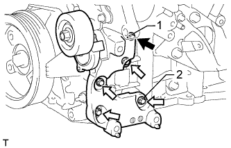 |
Temporarily install the V-ribbed belt tensioner with the 5 bolts.
| Item | Length |
| A | 70 mm (2.76 in.) |
| B | 33 mm (1.30 in.) |
 | Bolt A |
 | Bolt B |
Tighten bolts 1 and 2 in numerical order.
Tighten the other bolts.
| 5. INSTALL NO. 2 IDLER PULLEY SUB-ASSEMBLY |
for Separate Type:
Install the 2 idler pulley cover plates, 2 No. 2 idler pulleys and 2 No. 2 idler pulley cover plates with the 2 bolts.
for Integrated Type:
Install the 2 No. 2 idler pulleys with the 2 bolts.
| 6. INSTALL NO. 1 IDLER PULLEY SUB-ASSEMBLY |
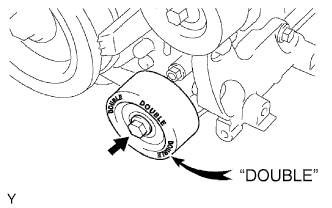 |
Install the No. 1 idler pulley with the bolt.
| 7. INSTALL WATER BY-PASS PIPE SUB-ASSEMBLY |
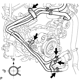 |
Install the water by-pass pipe with the 3 bolts.
Connect the 2 hoses.
| *a | Upward |
| *b | Rearward |
| 8. INSTALL INTAKE MANIFOLD |
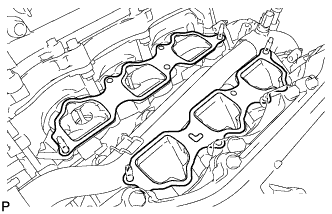 |
Set a new gasket on each cylinder head.
Set the intake manifold on the cylinder heads.
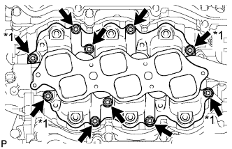 |
Install and uniformly tighten the 6 bolts and 4 nuts in several passes.
| *1 | Nut |
| 9. INSTALL FUEL INJECTOR ASSEMBLY |
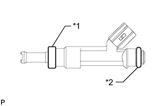 |
Install a new insulator to each fuel injector.
| *1 | New Insulator |
| *2 | New O-Ring |
Apply a light coat of spindle oil or gasoline to new O-rings and install one to each fuel injector.
Install the 6 injectors.
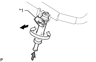 |
While turning each fuel injector left and right, install it to the fuel delivery pipe.
| *1 | Connector |
| Outward |
| Turn |
 | Push |
Position the fuel injectors with the connectors facing outward.
| 10. INSTALL FUEL DELIVERY PIPE SUB-ASSEMBLY |
Place the fuel delivery pipe together with the 6 fuel injectors on the intake manifold.
Temporarily install the 4 bolts, which are used to hold the fuel delivery pipe in place, to the intake manifold.
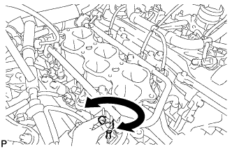 |
Check that the fuel injectors rotate smoothly.
| Turn |
Position the fuel injectors with the connectors facing outward.
Tighten the 4 bolts.
Connect the 6 fuel injector connectors.
| 11. INSTALL FUEL PIPE SUB-ASSEMBLY |
Install the No. 1 fuel pipe and No. 2 fuel pipe with the 2 bolts.
Connect the 2 fuel pipes (Click here).
| 12. INSTALL IGNITION COIL ASSEMBLY |
Install the 6 ignition coils with the 6 bolts.
| 13. INSTALL WIRING HARNESS CLAMP BRACKET |
Install the 7 wiring harness clamp brackets with the 7 bolts.
| 14. INSTALL NO. 2 EMISSION CONTROL VALVE SET |
Install the No. 2 emission control valve set with the 3 nuts.
| 15. INSTALL EMISSION CONTROL VALVE SET |
Install the emission control valve set with the 3 nuts.
| 16. INSTALL HEATER WATER PIPE SUB-ASSEMBLY |
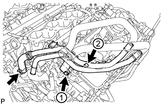 |
Temporarily install the heater water pipe, and then tighten the 2 bolts in the order shown in the illustration.
Connect the hose.
| 17. INSTALL NO. 1 WATER BY-PASS PIPE |
Connect the water by-pass pipe hoses to the water by-pass pipe and No. 1 water outlet pipe.
| 18. INSTALL ENGINE WIRE |