 |
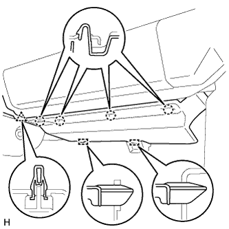
Detach the clip, 4 claws and 2 guides and remove the No. 2 instrument panel under cover sub-assembly.
CLEARANCE WARNING ECU > REMOVAL |
| 1. PRECAUTION |
| 2. DISCONNECT CABLE FROM NEGATIVE BATTERY TERMINAL |
Disconnect the cable from the negative (-) battery terminal.
| 3. REMOVE NO. 2 INSTRUMENT PANEL UNDER COVER SUB-ASSEMBLY |
|
Detach the clip, 4 claws and 2 guides and remove the No. 2 instrument panel under cover sub-assembly.
| 4. REMOVE LOWER INSTRUMENT PANEL |
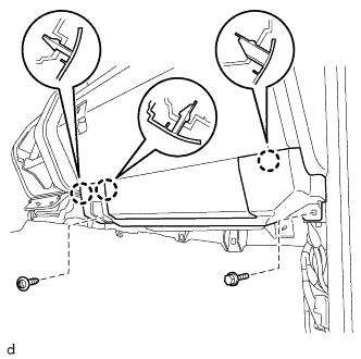 |
Remove the screw <D> and bolt <A>.
Detach the 3 claws and remove the lower instrument panel.
| 5. REMOVE LOWER NO. 2 INSTRUMENT PANEL AIRBAG ASSEMBLY |
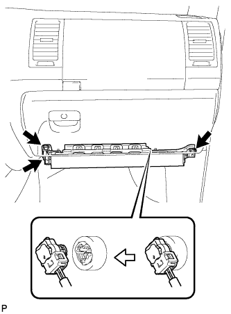 |
Remove the 3 bolts and remove the instrument panel airbag.
Disconnect the connector.
| 6. REMOVE NO.4 INSTRUMENT REGISTER SUB-ASSEMBLY |
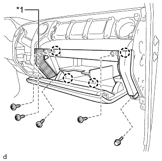 |
Apply protective tape as shown in the illustration.
| *1 | Protective Tape |
Remove the bolt <A> and 4 screws <F>.
Detach the 4 claws and remove the lower instrument panel finish panel sub-assembly RH.
| 7. REMOVE INSTRUMENT SIDE PANEL RH |
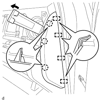 |
Using a moulding remover B, detach the 3 claws, 4 guides and remove the instrument side panel RH.
| 8. REMOVE NO.2 INSTRUMENT CLUSTER FINISH PANEL GARNISH |
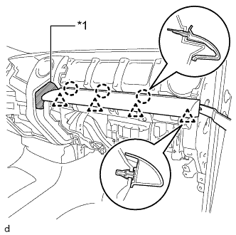 |
Apply protective tape as shown in the illustration.
| *1 | Protective Tape |
Using a moulding remover B, detach the 4 clips, 3 claws and remove the No. 2 instrument cluster finish panel garnish.
| 9. REMOVE LOWER INSTRUMENT PANEL FINISH PANEL SUB-ASSEMBLY RH |
|
Apply protective tape as shown in the illustration.
| *1 | Protective Tape |
Remove the bolt <A> and 4 screws <F>.
Detach the 4 claws and remove the lower instrument panel finish panel sub-assembly RH.
| 10. REMOVE CLEARANCE WARNING ECU WITH BRACKET |
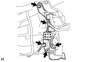 |
Disconnect the ECU connectors and detach the harness clamp.
Remove the bolt, nut and clearance warning ECU with bracket.
| 11. REMOVE CLEARANCE WARNING ECU ASSEMBLY |
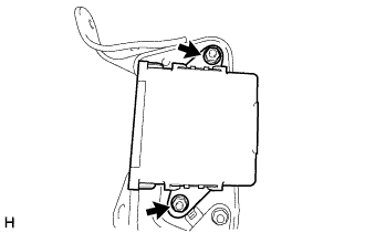 |
Remove the 2 nuts and clearance warning ECU assembly from the bracket.