UNLOCK WARNING SWITCH > INSTALLATION |
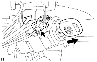
| 1. INSTALL UNLOCK WARNING SWITCH ASSEMBLY |
|
Attach the 2 claws to install the unlock warning switch assembly onto the upper steering column bracket assembly.
Remove the key.
Connect the connector.
 | Slide |
| 2. INSTALL UPPER STEERING COLUMN COVER (for Power Tilt and Power Telescopic Steering Column) |
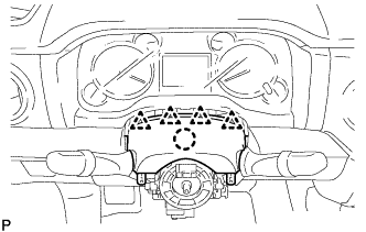 |
Attach the claw to install the upper steering column cover.
Attach the 4 clips.
| 3. INSTALL LOWER STEERING COLUMN COVER (for Power Tilt and Power Telescopic Steering Column) |
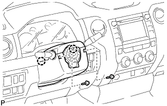 |
Attach the 2 claws to install the column cover.
Install the 2 screws.
| 4. INSTALL UPPER STEERING COLUMN COVER (for Manual Tilt and Manual Telescopic Steering Column) |
|
Attach the claw to install the upper steering column cover.
Attach the 4 clips.
| 5. INSTALL LOWER STEERING COLUMN COVER (for Manual Tilt and Manual Telescopic Steering Column) |
|
Attach the 2 claws to install the lower steering column cover.
Install the 2 screws.
| 6. INSTALL UPPER STEERING COLUMN COVER (for Manual Tilt) |
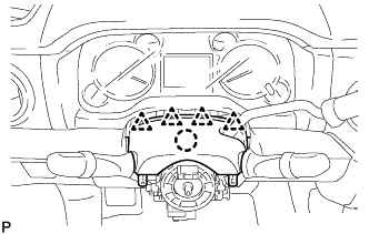 |
Attach the claw to install the upper steering column cover.
Attach the 4 clips.
| 7. INSTALL LOWER STEERING COLUMN COVER (for Manual Tilt) |
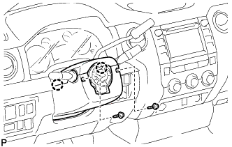 |
Attach the 2 claws to install the lower steering column cover.
Install the 2 screws.