 |
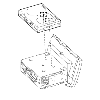
Attach the 2 guides to install the stereo component tuner assembly as shown in the illustration.
SATELLITE RADIO TUNER (for Floor Shift Type) > INSTALLATION |
| 1. INSTALL STEREO COMPONENT TUNER ASSEMBLY |
|
Attach the 2 guides to install the stereo component tuner assembly as shown in the illustration.
| 2. INSTALL NO. 2 RADIO RECEIVER BRACKET |
Install the No. 2 radio receiver bracket with the 5 bolts.
| 3. INSTALL NO. 1 RADIO RECEIVER BRACKET |
Install the No. 1 radio receiver bracket with the 5 bolts.
| 4. INSTALL NO. 1 NAVIGATION WIRE |
Connect each connector to install the No. 1 navigation wire.
| 5. INSTALL RADIO AND DISPLAY RECEIVER ASSEMBLY |
Connect each connector.
Insert the radio and display receiver assembly with bracket and attach the 2 guides and 3 clips on its backside.
Install the radio and display receiver assembly with bracket with the 4 bolts.
| 6. INSTALL AIR CONDITIONING CONTROL ASSEMBLY |
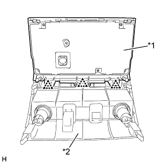 |
Attach the 3 clips to install the air conditioning control assembly to the center lower instrument panel finish panel.
| *1 | Air Conditioning Control Assembly |
| *2 | Center Lower Instrument Panel Finish Panel |
Put protective tape around the air conditioning control assembly.
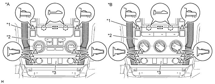
| *A | for Automatic Air Conditioning System | *B | for Manual Air Conditioning System |
| *1 | Protective Tape | *2 | Air Conditioning Control Assembly |
| *3 | Center Lower Instrument Panel Finish Panel | - | - |
Connect each connector.
Attach the 8 clips, 2 claws and guide to install the air conditioning control assembly together with the center lower instrument panel finish panel.
| 7. INSTALL UPPER CONSOLE PANEL SUB-ASSEMBLY |
Attach the 12 clips to install the upper console panel sub-assembly.
| 8. INSTALL REAR UPPER CONSOLE PANEL SUB-ASSEMBLY |
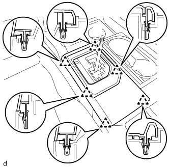 |
Attach the 6 clips to install the upper rear console panel sub-assembly.
| 9. INSTALL SHIFT LEVER KNOB SUB-ASSEMBLY |
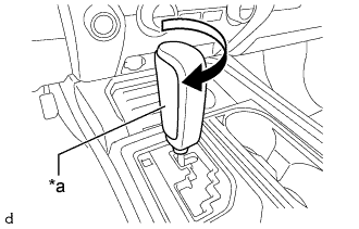 |
Twist the shift lever knob sub-assembly in the direction indicated by the arrow to install it.
| *a | Leather Portion |
| 10. CONNECT CABLE TO NEGATIVE BATTERY TERMINAL |