INSTRUMENT PANEL SPEAKER (for CrewMax) > INSPECTION |
| 1. INSPECT FRONT NO. 2 SPEAKER ASSEMBLY (for Standard) |
When there is a malfunction such as noise from a speaker or no sound at all, replace the speaker with a new one and check that the malfunction disappears.
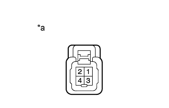
| 2. INSPECT FRONT NO. 2 SPEAKER ASSEMBLY (for 12 Speakers) |
|
Measure the resistance according to the value(s) in the table below.
| Tester Connection | Condition | Specified Condition |
| 3 - 4 | Always | 1.5 to 2.5 Ω |
| 3 - 1 | Always | Below 1 Ω |
| 4 - 2 |
| *a | Component without harness connected (Front No. 2 Speaker Assembly) |
| 3. INSPECT FRONT NO. 4 SPEAKER ASSEMBLY (for Standard) |
Temporarily replace the front No. 4 speaker assembly with a new or normally functioning one.
| 4. INSPECT FRONT NO. 4 SPEAKER ASSEMBLY (for 12 Speakers) |
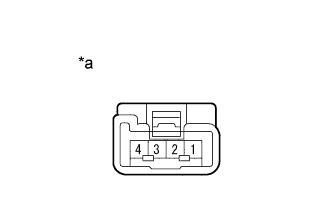 |
Measure the resistance according to the value(s) in the table below.
| Tester Connection | Condition | Specified Condition |
| 1 - 2 | Always | 1.5 to 2.1 Ω |
| *a | Component without harness connected (Front No. 4 Speaker Assembly) |