 |
Apply protective tape as shown in the illustration.
| *1 | Protective Tape |
INSTRUMENT PANEL SPEAKER (for CrewMax) > REMOVAL |
| 1. REMOVE FRONT PILLAR GARNISH LH |
|
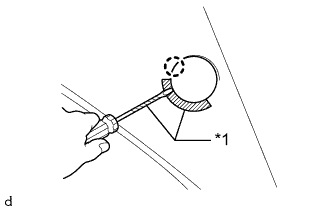
Apply protective tape as shown in the illustration.
| *1 | Protective Tape |
Using a screwdriver, detach the claw and open the cover.
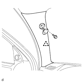 |
Remove the bolt.
Detach the clip and remove the front pillar garnish LH.
Protect the curtain shield airbag assembly.
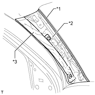 |
Completely cover the curtain shield airbag assembly with a cloth or nylon sheet and secure the ends of the cover with adhesive tape as shown in the illustration.
| *1 | Adhesive Tape |
| *2 | Protective Cover |
| *3 | Curtain Shield Airbag Assembly |
| 2. REMOVE FRONT PILLAR GARNISH RH |
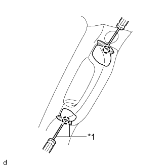 |
Apply protective tape as shown in the illustration.
| *1 | Protective Tape |
Using a screwdriver, detach the 2 claws and open the 2 assist grip covers.
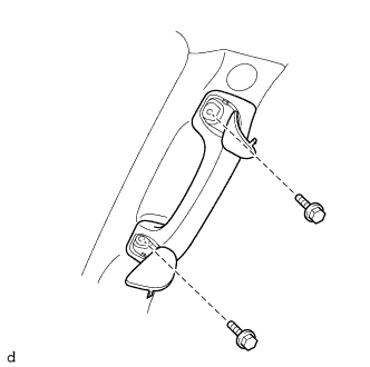 |
Remove the 2 bolts and front assist grip sub-assembly from the front pillar garnish RH.
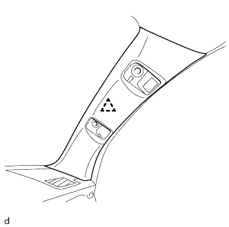 |
Detach the clip and remove the front pillar garnish RH.
Protect the curtain shield airbag assembly.
Completely cover the curtain shield airbag assembly with a cloth or nylon sheet and secure the ends of the cover with adhesive tape.
| 3. REMOVE NO. 1 INSTRUMENT PANEL SPEAKER PANEL SUB-ASSEMBLY |
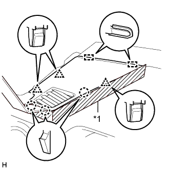 |
| *1 | Protective Tape |
Apply protective tape as shown in the illustration.
Using moulding remover B, detach the 3 clips, 3 claws and 2 guides and remove the No. 1 instrument panel speaker panel sub-assembly.
| 4. REMOVE NO. 2 INSTRUMENT PANEL SPEAKER PANEL SUB-ASSEMBLY |
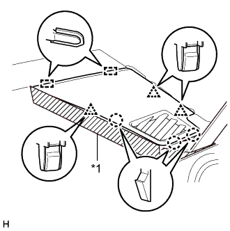 |
| *1 | Protective Tape |
Apply protective tape as shown in the illustration.
Using moulding remover B, detach the 3 clips, 3 claws and 2 guides and remove the No. 2 instrument panel speaker panel sub-assembly.
| 5. REMOVE FRONT NO. 2 SPEAKER ASSEMBLY LH |
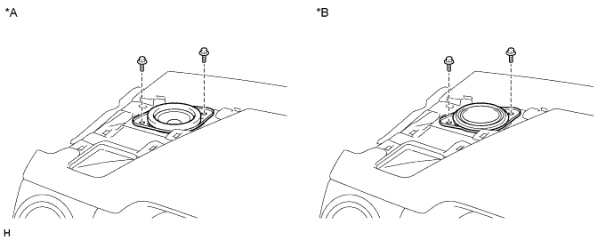
| *A | for Standard | *B | for 12 Speakers |
Remove the 2 bolts.
Disconnect the connector and remove the front No. 2 speaker assembly LH.
| 6. REMOVE FRONT NO. 2 SPEAKER ASSEMBLY RH |
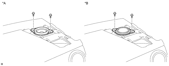
| *A | for Standard | *B | for 12 Speakers |
Remove the 2 bolts.
Disconnect the connector and remove the front No. 2 speaker assembly RH.
| 7. REMOVE NO. 1 SPEAKER HOLE COVER |
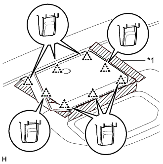 |
| *1 | Protective Tape |
Apply protective tape as shown in the illustration.
Using moulding remover B, detach the 8 clips and remove the No. 1 speaker hole cover.
| 8. REMOVE FRONT NO. 4 SPEAKER ASSEMBLY (for 12 Speakers) |
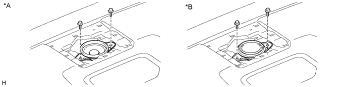
| *A | for Standard | *B | for 12 Speakers |
Remove the 2 bolts.
Disconnect the connector and remove the front No. 4 speaker assembly.