BACK WINDOW GLASS (for CrewMax) > REMOVAL |
| 1. DISCONNECT CABLE FROM NEGATIVE BATTERY TERMINAL |
| 2. REMOVE REAR ROOF DRIP SIDE FINISH MOULDING LH |
|
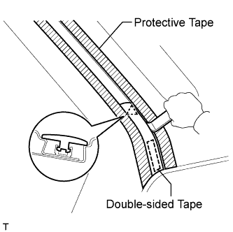
Put protective tape around the moulding.
Using a heat light, heat the moulding.
Using a moulding remover, detach the clip and remove the moulding.
| 3. REMOVE REAR ROOF DRIP SIDE FINISH MOULDING RH |
| 4. REMOVE REAR SEAT ASSEMBLY LH |
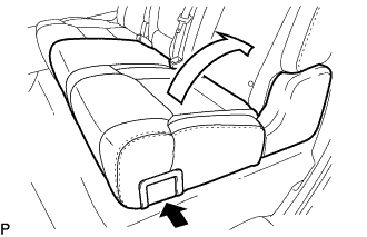 |
Pull the No. 1 reclining adjuster release handle LH and fold up the seat cushion.
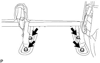 |
Remove the 4 bolts and rear seat assembly LH.
| 5. REMOVE REAR SEAT ASSEMBLY RH |
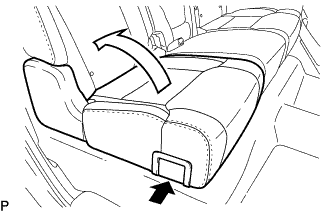 |
Pull the No. 1 reclining adjuster release handle RH and fold up the seat cushion.
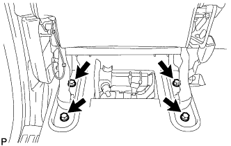 |
Remove the 4 bolts and rear seat assembly RH.
| 6. REMOVE REAR DOOR SCUFF PLATE LH |
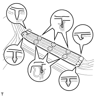 |
Detach the 8 claws and 2 clips, and remove the rear door scuff plate LH.
| 7. REMOVE REAR DOOR SCUFF PLATE RH |
| 8. REMOVE REAR DOOR OPENING TRIM WEATHERSTRIP LH |
Partially remove the rear door opening trim weatherstrip LH so that the lower quarter trim panel LH and front quarter trim panel LH can be removed .
| 9. REMOVE REAR DOOR OPENING TRIM WEATHERSTRIP RH |
| 10. REMOVE FRONT SHOULDER BELT ANCHOR PLATE SUB-ASSEMBLY LH |
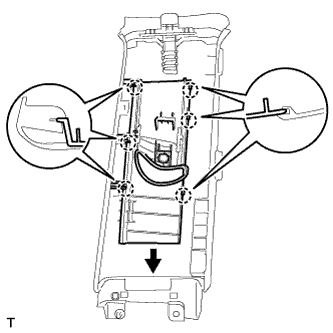 |
Detach the 6 claws of the front shoulder belt anchor plate sub-assembly LH, and slide the front shoulder belt anchor plate sub-assembly LH in the direction of the arrow to remove it.
| 11. REMOVE FRONT SHOULDER BELT ANCHOR PLATE SUB-ASSEMBLY RH |
| 12. REMOVE NO. 1 BOX SPEAKER ASSEMBLY |
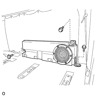 |
Remove the 3 bolts.
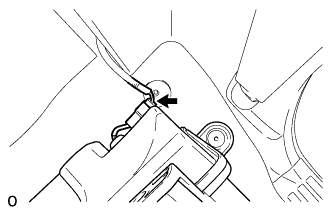 |
Disconnect the connector and remove the No. 1 box speaker assembly.
| 13. REMOVE LOWER QUARTER TRIM PANEL ASSEMBLY LH |
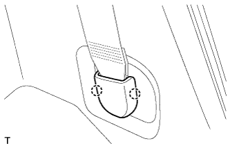 |
Detach the 2 claws and remove the cover.
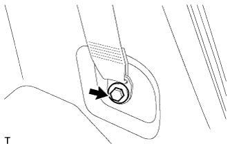 |
Loosen the bolt and disconnect the rear seat outer belt assembly.
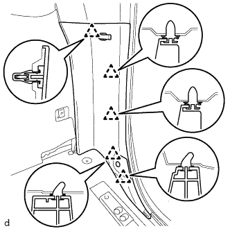 |
Detach the 5 clips and remove the lower quarter trim panel assembly LH.
| 14. REMOVE LOWER QUARTER TRIM PANEL ASSEMBLY RH |
| 15. REMOVE FRONT QUARTER TRIM PANEL ASSEMBLY LH |
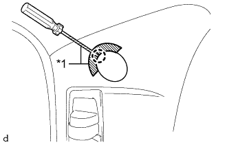 |
Apply protective tape as shown in the illustration.
| *1 | Protective Tape |
Using a screwdriver, detach the claw and open the cover.
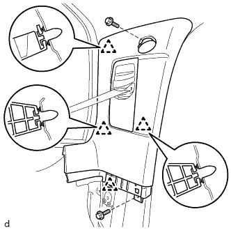 |
Remove the 2 bolts.
Detach the 4 clips and remove the front quarter trim panel assembly LH.
Pass the rear seat outer belt assembly through the hole of the front quarter trim panel assembly LH.
| 16. REMOVE FRONT QUARTER TRIM PANEL ASSEMBLY RH |
| 17. REMOVE ASSIST GRIP SUB-ASSEMBLY |
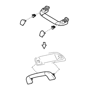 |
Assemble the assist grip sub-assembly as shown in the illustration.
Attach the 2 clips to install the assist grip sub-assembly.
| 18. REMOVE NO. 1 ROOM LIGHT ASSEMBLY |
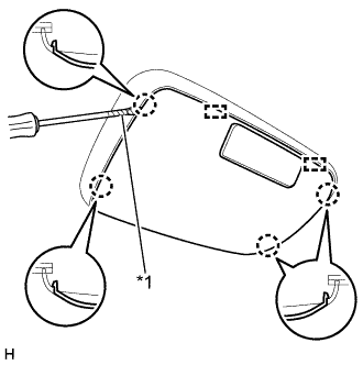 |
Using a screwdriver, detach the 4 claws and 2 guides and remove the No. 1 room light lens.
| *1 | Tape |
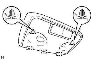 |
Detach the 2 clips and 3 guides and remove the No. 1 room light assembly.
| 19. TEMPORARILY REMOVE ROOF HEADLINING ASSEMBLY |
It is not necessary to completely remove the roof headlining. Slightly lower the rear section of the roof headlining so that the back window glass can be removed in a later step.
| 20. REMOVE BACK DOOR SERVICE HOLE COVER |
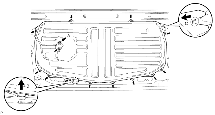
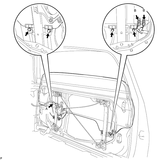
Remove the back window regulator connector labeled A.
Remove the 12 bolts and nut.
Lift the cover upwards to detach the claw labeled B. Then slide the cover to the left to disengage the retainer labeled C and remove the cover.
| 21. REMOVE OUTER BACK DOOR GLASS WEATHERSTRIP ASSEMBLY |
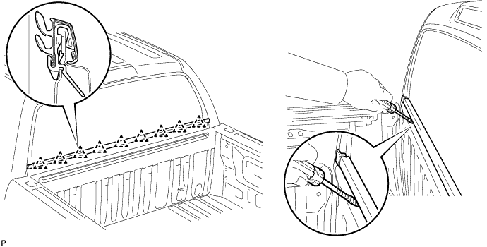
Using a screwdriver, detach the 9 claws and remove the weatherstrip.
| 22. REMOVE INNER BACK DOOR GLASS WEATHERSTRIP |
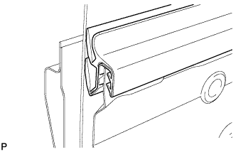 |
Using a screwdriver, remove the weatherstrip.
| 23. REMOVE BACK DOOR GLASS RUN |
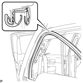 |
Remove the glass run.
| 24. REMOVE BACK WINDOW GLASS |
Connect the cable to the negative (-) battery terminal.
Connect the back window regulator connector labeled A.
Move the back window glass until the bolts appear in the service holes.
Disconnect the back window regulator connector labeled A.
Disconnect the cable from the negative battery (-) terminal.
Disconnect the 2 defogger connectors labeled B.
Remove the 4 bolts.
Remove the back window glass.
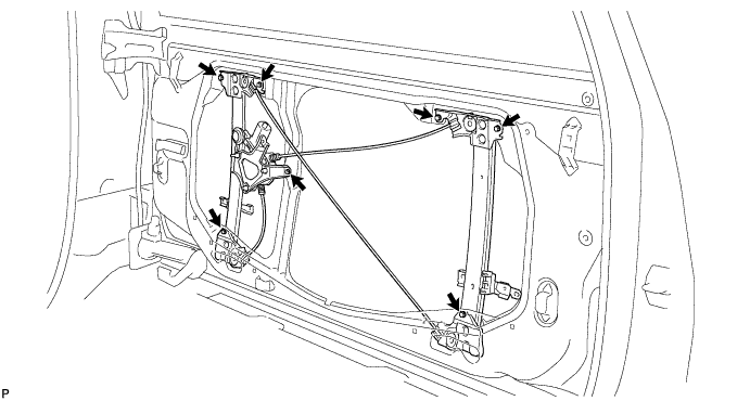
| 25. REMOVE BACK DOOR POWER WINDOW REGULATOR SUB-ASSEMBLY |
Remove the 7 bolts and back window regulator.
| 26. REMOVE BACK DOOR POWER WINDOW REGULATOR MOTOR |
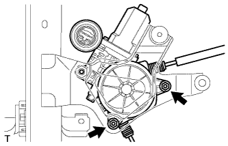 |
Remove the 2 nuts and motor.
Remove the 2 screws and cover.
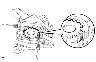 |
Remove the drum and wire guide from the motor.
| 27. REMOVE BACK WINDOW OUTSIDE MOULDING |
Put a 4 mm (0.157 in.) drill bit into a drill.
Wind tape around the drill bit 5 mm (0.196 in.) from the tip of the drill, as shown in the illustration.
Lightly press the drill against the rivets, drill off the flanges of the rivets, and remove the 16 rivets.
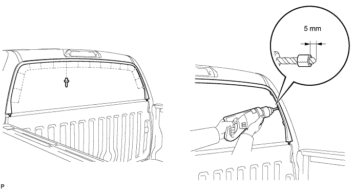
Using a vacuum cleaner, remove the rivet fragments and shavings from the drilled areas.
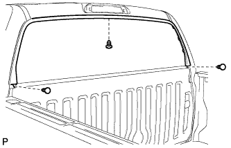 |
Remove the 3 clips and back window outside moulding.
| 28. REMOVE UPPER CAB REAR PILLAR PLATE LH |
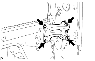 |
Remove the 4 bolts and upper plate.
| 29. REMOVE UPPER CAB REAR PILLAR PLATE RH |