 |
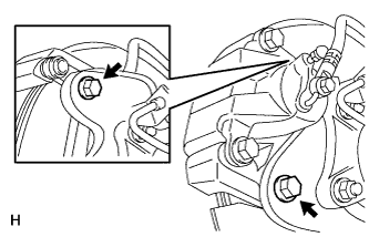
Remove the 2 bolts and disconnect the rear disc brake cylinder.
- NOTICE:
- Do not disconnect the flexible hose from the disc brake cylinder.
- Do not twist or bend the flexible hose.
REAR AXLE HUB BOLT > REPLACEMENT |
| 1. REMOVE REAR WHEEL LH |
| 2. DISCONNECT REAR DISC BRAKE CYLINDER ASSEMBLY LH |
|
Remove the 2 bolts and disconnect the rear disc brake cylinder.
Hang the disc brake cylinder with a piece of wire.
| 3. REMOVE REAR DISC LH |
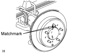 |
Put matchmarks on the rear disc and axle hub if planning to reuse the disc.
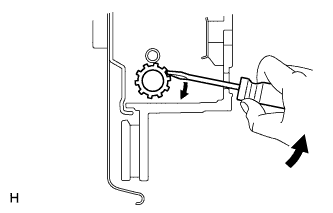 |
Turn the shoe adjuster until the disc turns freely, and then remove the disc.
| 4. REMOVE PARKING BRAKE SHOE RETURN TENSION SPRING LH |
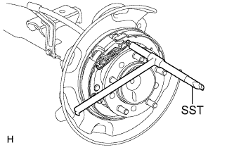 |
Using SST, remove the return spring.
| 5. REMOVE NO. 1 PARKING BRAKE SHOE ASSEMBLY LH |
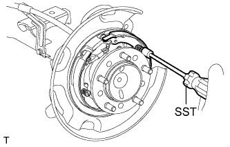 |
Using SST, remove the shoe hold down spring cup, compression spring and shoe hold down spring pin.
Disconnect the tension spring.
Remove the No. 1 parking brake shoe and shoe adjuster screw set.
| 6. REMOVE NO. 2 PARKING BRAKE SHOE ASSEMBLY LH |
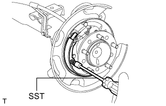 |
Using SST, remove the shoe hold down spring cup, compression spring and shoe hold down spring pin.
Remove the No. 2 parking brake shoe.
| 7. REMOVE PARKING BRAKE SHOE LEVER SUB-ASSEMBLY LH |
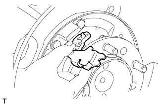 |
Disconnect the No. 3 parking brake cable from the parking brake shoe lever.
Remove the parking brake shoe lever.
| 8. REMOVE REAR AXLE LH HUB BOLT |
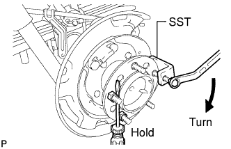 |
Using SST and a screwdriver or equivalent to hold the axle hub, remove the hub bolt.
| 9. INSTALL REAR AXLE LH HUB BOLT |
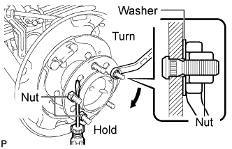 |
Temporarily install a washer and hub nut to a new hub bolt as shown in the illustration.
Using a screwdriver or equivalent to hold the hub, turn the hub nut until the bottom surface of the hub bolt head touches the axle hub.
Remove the washer and hub nut.
| 10. INSTALL PARKING BRAKE SHOE LEVER SUB-ASSEMBLY LH |
Apply high temperature grease to the parking brake shoe lever.
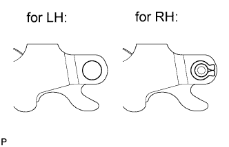 |
Install the parking brake shoe lever to the No. 3 parking brake cable.
| 11. INSTALL NO. 2 PARKING BRAKE SHOE ASSEMBLY LH |
Apply high temperature grease to the areas of the backing plate that contact the shoe.
|
Using SST, install the No. 2 parking brake shoe with the shoe hold down spring pin, compression spring and shoe hold down spring cup.
| 12. INSTALL NO. 1 PARKING BRAKE SHOE ASSEMBLY LH |
Apply high temperature grease to the areas of the backing plate that contact the shoe.
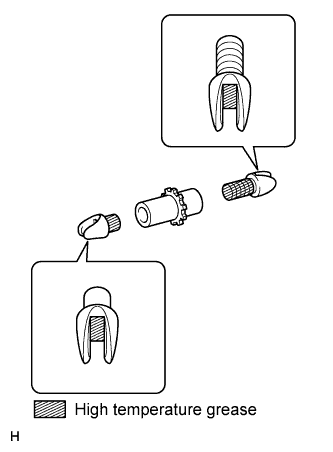 |
Apply the high temperature grease to the areas of the shoe adjusting screw set shown in the illustration.
Set the parking brake shoe and shoe adjuster screw set in place.
Connect the tension spring.
|
Using SST, install the No. 1 parking brake shoe with the shoe hold down spring pin, compression spring and shoe hold down spring cup.
| 13. INSTALL PARKING BRAKE SHOE RETURN TENSION SPRING LH |
|
Using SST, install the shoe return spring.
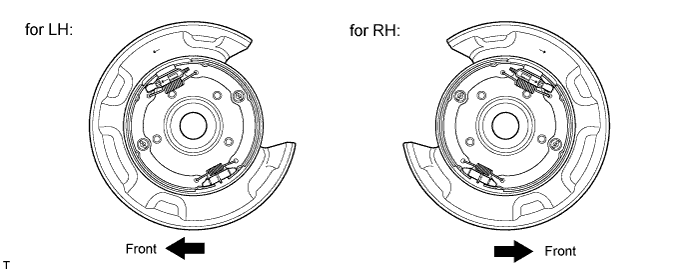
| 14. CHECK PARKING BRAKE INSTALLATION |
Check that each part is installed properly.
| 15. INSTALL REAR DISC LH |
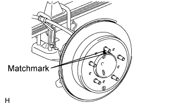 |
Align the matchmarks and install the rear disc.
| 16. ADJUST PARKING BRAKE SHOE CLEARANCE |
Temporarily install the hub nuts.
Remove the hole plug.
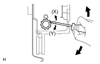 |
Insert a screwdriver into the adjustment hole of the disc. Rotate the adjustment wheel in the "X" direction until the shoes are locked. Then rotate the adjustment wheel in the "Y" direction 8 notches.
Check that the disc can be rotated smoothly. If not, rotate the adjustment wheel in the "Y" direction and check again.
Install the hole plug.
Remove the hub nuts.
| 17. CONNECT REAR DISC BRAKE CYLINDER ASSEMBLY LH |
|
Connect the rear disc brake cylinder with 2 new bolts.
| 18. INSTALL REAR WHEEL LH |
| 19. CHECK PARKING BRAKE TRAVEL |
Firmly depress the parking brake pedal.
Release the parking brake.
Slowly depress the parking brake pedal with a force of approximately 300 N (31 kgf, 67.4 lbf) and count the number of clicks.
| 20. ADJUST PARKING BRAKE TRAVEL |
Depress the parking brake pedal.
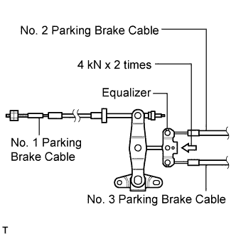 |
Apply load equivalent to 4 kN (408 kgf, 899.2 lbf) on equalizer twice to pull No. 2 and No. 3 parking brake cable to remove initial elongation.
Release the parking brake pedal to the original position.
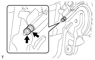 |
Loosen the pedal side No. 1 parking brake cable lock nut.
Turn the pedal side No. 1 parking brake cable adjustment nut until the parking brake pedal travel is correct.
| Pedal Load | Specified Condition |
| 300 N (31 kgf, 67.4 lbf) | 6 to 9 clicks |
Using a wrench or equivalent to hold the adjustment nut, tighten the lock nut.
Additionally, excessive pedal travel can be adjusted on the No. 1 parking brake cable underbody side as follows.
Release the parking brake pedal to the original position.
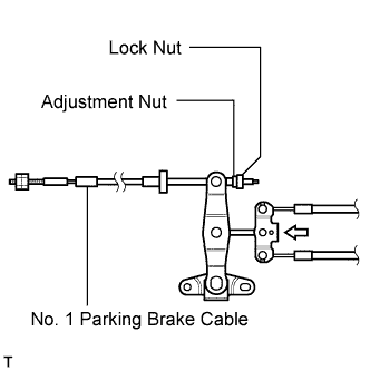 |
Loosen the underbody side No. 1 parking brake cable lock nut.
Turn the underbody side No. 1 parking brake cable adjustment nut until the parking brake pedal travel is correct.
| Pedal Load | Specified Condition |
| 300 N (31 kgf, 67.4 lbf) | 6 to 9 clicks |
Tighten the No. 1 parking brake cable underbody lock nut.
Depress and release the parking brake pedal 3 or 4 times. Then check the number of clicks when depressing the pedal.
Check whether the parking brake drags or not.
If the parking brake drags, adjust the shoe clearance.
When operating the parking brake pedal, check that the parking brake pedal indicator light comes on at the first notch.
If not, adjust the parking brake switch installation position.