Home › ENGINE ยท 3UR-FE › ENGINE MECHANICAL › ENGINE UNIT

ENGINE UNIT > INSTALLATION

for Preparation Click here


1. INSTALL IGNITION COIL ASSEMBLY
  1. Install the 8 ignition coils with the 8 bolts.

    Torque:
    10 N*m{ 102 kgf*cm , 7 ft.*lbf }


2. INSTALL KNOCK SENSOR

HINT:
Perform "Inspection After Repairs" after replacing the knock sensor (Click here).


    A152496E12
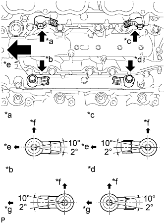
  1. Install the 4 knock sensors with the 4 bolts so that the knock sensors are angled as shown in the illustration.

    Torque:
    20 N*m{ 204 kgf*cm , 15 ft.*lbf }

    Text in Illustration 
    *a
    Bank 2 Sensor 1
    *b
    Bank 1 Sensor 1
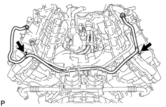
    *c
    Bank 2 Sensor 2
    *d
    Bank 1 Sensor 2
    *e
    Front
    *f
    Upper
    *g
    Rear

    NOTICE:
    The acceptable installation angle of the knock sensor is between 10° upward and 2° downward from the horizontal position.
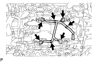
  1. Connect the 4 knock sensor connectors.


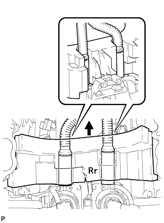
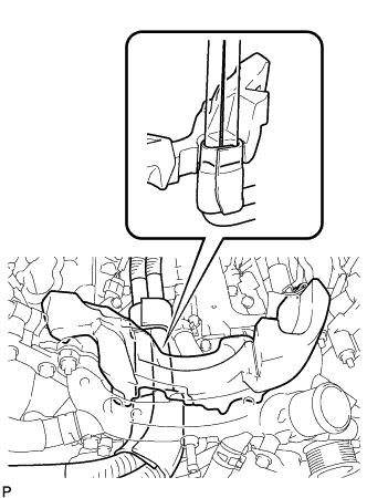
3. INSTALL SEPARATOR CASE
  1. Install the separator case with the 4 bolts.

    Torque:
    10 N*m{ 102 kgf*cm , 7 ft.*lbf }


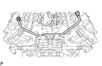
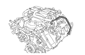
4. INSTALL ENGINE WIRE


A160651
  1. Connect the 3 clamps and 4 knock sensor connectors.


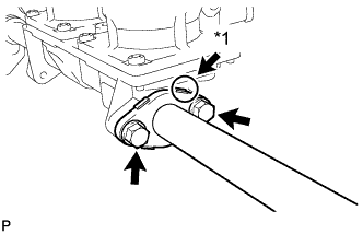
5. INSTALL NO. 3 AIR TUBE


    A158585E03
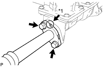
  1. Install a new gasket and the No. 3 air tube with the 2 bolts.

    Torque:
    10 N*m{ 102 kgf*cm , 7 ft.*lbf }

    Text in Illustration 
    *1
    Identification Color

    NOTICE:
    Make sure the gasket's claws are not caught between the air tube and air switching valve.

    HINT:
    The identification color on the flange is orange.


6. INSTALL NO. 2 AIR TUBE


    A158584E03
  1. Install a new gasket and the No. 2 air tube with the 2 bolts.

    Torque:
    10 N*m{ 102 kgf*cm , 7 ft.*lbf }

    Text in Illustration 
    *1
    Identification Color

    NOTICE:
    Make sure the gasket's claws are not caught between the air tube and air switching valve.

    HINT:
    The identification color on the flange is blue.


7. INSTALL AIR SWITCHING VALVE ASSEMBLY
  1. Install the air switching valve assembly with the 3 bolts to the No. 1 heat exchanger cover.

    Torque:
    21 N*m{ 214 kgf*cm , 15 ft.*lbf }

  1. Connect the 2 air switching valve assembly connectors.

  1. Install the bracket to the air switching valve assembly with the bolt.

    Torque:
    8.0 N*m{ 82 kgf*cm , 71 in.*lbf }

  1. Connect the knock sensor connector.


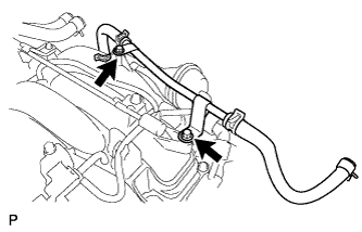
8. INSTALL WATER BY-PASS PIPE SUB-ASSEMBLY
  1. Connect the No. 2 water by-pass hose and No. 3 water by-pass hose to the water by-pass pipe sub-assembly, and slide the 2 clamps to secure the hoses.

  1. Install the water by-pass pipe sub-assembly with the 2 bolts.

    Torque:
    10 N*m{ 102 kgf*cm , 7 ft.*lbf }

  1. Connect the air tube sub-assembly with the bolt.

    Torque:
    10 N*m{ 102 kgf*cm , 7 ft.*lbf }


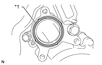
9. INSTALL WATER INLET HOUSING


    A162555E05
  1. Install a new gasket to the timing chain cover sub-assembly.
    Text in Illustration 
    *1
    Gasket

  1. Install the water inlet housing with the 3 bolts.

    Torque:
    21 N*m{ 214 kgf*cm , 15 ft.*lbf }


10. INSTALL AIR TUBE
  1. Connect the 2 hoses.

  1. Install the air tube sub-assembly with the bolt.

    Torque:
    10 N*m{ 102 kgf*cm , 7 ft.*lbf }


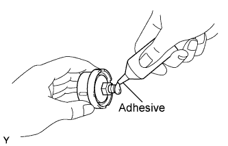
11. INSTALL OIL PRESSURE SENDER GAUGE ASSEMBLY


    A118764E02
  1. Apply adhesive to 2 or 3 threads of the oil pressure sender gauge.

    Adhesive:
    Toyota Genuine Adhesive 1344, Three Bond 1344 or equivalent


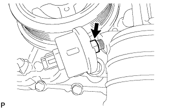
    A162467
  1. Install the oil pressure sender gauge.

    Torque:
    15 N*m{ 153 kgf*cm , 11 ft.*lbf }

    NOTICE:
    Do not start the engine within 1 hour after installation.


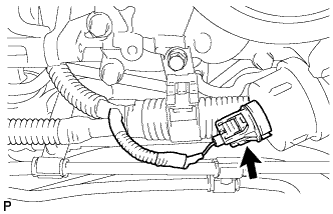
    A163657
  1. Connect the sender gauge connector.


12. INSTALL NO. 1 IDLER PULLEY SUB-ASSEMBLY
  1. Install the No. 1 idler pulley sub-assembly with the bolt.

    Torque:
    43 N*m{ 438 kgf*cm , 32 ft.*lbf }


13. INSTALL WATER PUMP PULLEY
  1. Temporarily install the water pump pulley with the 4 bolts.

  1. Using SST, hold the water pump pulley and tighten the 4 bolts.

    SST
    09960-10010   (09962-01000, 09963-01000)

    Torque:
    21 N*m{ 214 kgf*cm , 15 ft.*lbf }


14. INSTALL NO. 1 ENGINE COVER


A158656

NOTICE:
Make sure that the No. 1 engine cover is level with the top surface of the intake port of the cylinder head for 1 and 2.

HINT:
  1. Align the No. 1 engine cover cutouts with the air tube.
  2. Align the No. 1 engine cover with the air switching valve surface and cylinder head wall.


15. INSTALL NO. 2 ENGINE COVER


A307709

NOTICE:
Make sure that the No. 2 engine cover is level with the top surface of the intake port if the cylinder head.

HINT:
  1. Align the No. 2 engine cover cutout with the air tube.
  2. Align the No. 2 engine cover with the front water by-pass joint and cylinder head wall.


16. INSTALL FRONT WATER BY-PASS JOINT
  1. Install 2 new gaskets and the front water by-pass joint with the 4 nuts to the cylinder head.

    Torque:
    21 N*m{ 214 kgf*cm , 15 ft.*lbf }

  1. Connect the No. 2 water by-pass hose to the front water by-pass joint, and slide the clamp to secure the hose.


17. INSTALL NO. 1 WATER BY-PASS HOSE
  1. Connect the No. 1 water by-pass hose to the inlet water housing and front water by-pass joint, and slide the 2 clamps to secure the hoses.


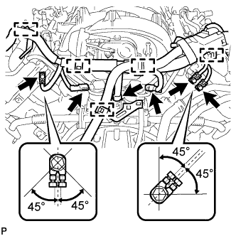
18. INSTALL NO. 2 WATER BY-PASS PIPE
  1. Connect the 4 hoses to the No. 2 water by-pass pipe, and slide the 4 clamps to secure the hoses.

  1. Install the No. 2 water by-pass pipe with the 3 bolts.

    Torque:
    10 N*m{ 102 kgf*cm , 7 ft.*lbf }


19. INSTALL FUEL TUBE SUB-ASSEMBLY


A256360


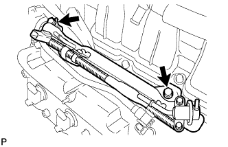
20. INSTALL NO. 2 FUEL TUBE SUB-ASSEMBLY


    A256359
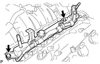
  1. Install the No. 2 fuel tube with the 2 bolts.

    Torque:
    10 N*m{ 102 kgf*cm , 7 ft.*lbf }


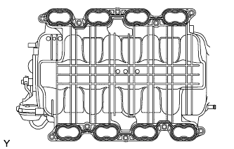
21. INSTALL INTAKE MANIFOLD


    A162094
  1. Place 2 new gaskets on the intake manifold.

  1. Place the intake manifold on the cylinder head sub-assembly.

  1. Install and uniformly tighten the 8 bolts and 2 nuts in several steps.

    Torque:
    21 N*m{ 214 kgf*cm , 15 ft.*lbf }

  1. Install the wire harness clamp bracket to the intake manifold with the bolt.

    Torque:
    8.0 N*m{ 82 kgf*cm , 71 in.*lbf }

  1. Attach the 3 wire harness clamps to the 3 wire harness clamp brackets.

  1. Install the No. 1 tube with the 2 bolts.

    Torque:
    8.2 N*m{ 84 kgf*cm , 73 in.*lbf }

  1. Connect the union to connector tube hose to the No. 1 tube, and slide the clamp to secure the hose.

  1. Connect the purge line hose to the purge VSV, and slide the clamp to secure the hose.

  1. Connect the 2 vacuum switching valve connectors.

  1. Connect the ventilation hose to the intake manifold, and slide the clamp to secure the hose.

  1. Connect the 2 water by-pass hoses to the inlet water housing and front water by-pass joint, and slide the 2 clamps to secure the hose.

  1. Connect the throttle body connector to the throttle body assembly.

  1. Install the No. 3 engine cover.

  1. Install the No. 1 engine cover sub-assembly.


22. INSTALL NO. 1 TUBE


    A163943
  1. Install the No. 1 tube with the 2 bolts.

    Torque:
    10 N*m{ 102 kgf*cm , 7 ft.*lbf }


23. CONNECT VENTILATION HOSE ASSEMBLY
  1. Connect the ventilation hose assembly to the ventilation pipe of the cylinder head cover sub-assembly and cylinder head cover sub-assembly LH, and slide the 2 clamps to secure the hose.


24. INSTALL FUEL DELIVERY PIPE SUB-ASSEMBLY RH


    A256330
  1. Install the 2 delivery pipe spacers and 4 insulators to the cylinder head RH.

  1. Install the delivery pipe (with injectors) to the cylinder head RH.


  1. Install the 2 bolts.

    Torque:
    21 N*m{ 214 kgf*cm , 15 ft.*lbf }


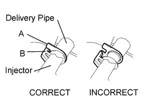
    NOTICE:
    A163659E01
    Make sure that the part of the injector labeled B is between the parts of the delivery pipe labeled A.

  1. Install the No. 3 engine cover.


    A161422
  1. Connect the No. 6 wire harness connector.

  1. Connect the ventilation hose.


25. INSTALL FUEL DELIVERY PIPE SUB-ASSEMBLY LH


    A256331
  1. Install the 2 delivery pipe spacers and 4 insulators to the cylinder head LH.

  1. Install the delivery pipe (with injectors) to the cylinder head LH.


  1. Install the 2 bolts.

    Torque:
    21 N*m{ 214 kgf*cm , 15 ft.*lbf }


    NOTICE:
    A163659E01
    Make sure that the part of the injector labeled B is between the parts of the delivery pipe labeled A.

  1. Connect the No. 7 wire harness connector.

  1. Install the No. 1 engine cover.


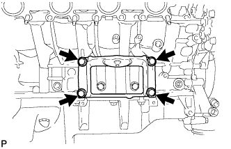
26. INSTALL NO. 1 ENGINE MOUNTING BRACKET LH


A160648
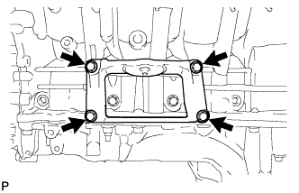
  1. Install the mounting bracket with the 4 bolts.

    Torque:
    35 N*m{ 357 kgf*cm , 26 ft.*lbf }


27. INSTALL NO. 1 ENGINE MOUNTING BRACKET RH


A160649
  1. Install the mounting bracket with the 4 bolts.

    Torque:
    35 N*m{ 357 kgf*cm , 26 ft.*lbf }


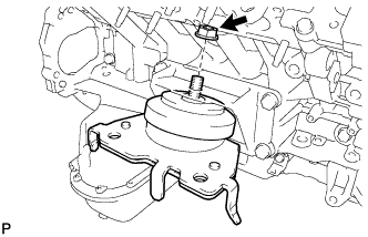
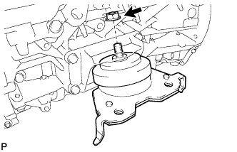
28. INSTALL FRONT ENGINE MOUNTING INSULATOR RH


    A163786
  1. Install the mounting insulator with the nut.

    Torque:
    72 N*m{ 734 kgf*cm , 53 ft.*lbf }


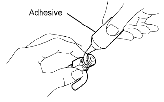
29. INSTALL CYLINDER BLOCK WATER DRAIN COCK SUB-ASSEMBLY


A076531E01
  1. Apply adhesive to 2 or 3 threads of the drain cocks.

    Adhesive:
    Toyota Genuine Adhesive 1344, Three Bond 1344 or equivalent


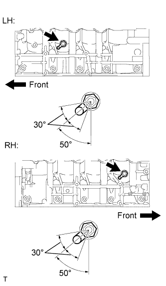
    A163841E01
  1. Install the water drain cocks.

    Torque:
    30 N*m{ 306 kgf*cm , 22 ft.*lbf }

  1. Further tighten the drain cocks within 360° so that the drain cock pipes are within the range shown in the illustration.

    NOTICE:
    1. Do not rotate the drain cocks more than 1 revolution (360°) after tightening the drain cocks to the specified torque.
    2. Do not loosen the drain cocks to adjust them. If an adjustment is necessary, remove the drain cocks and reinstall them.

  1. Install the water drain cock plugs to the water drain cocks.

    Torque:
    13 N*m{ 133 kgf*cm , 10 ft.*lbf }


30. INSTALL FRONT ENGINE MOUNTING INSULATOR LH


    A163787
  1. Install the mounting insulator with the nut.

    Torque:
    72 N*m{ 734 kgf*cm , 53 ft.*lbf }


31. INSTALL NO. 1 FUEL PIPE SUB-ASSEMBLY


A308965
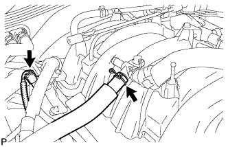
  1. Install the No. 1 fuel pipe (Click here).


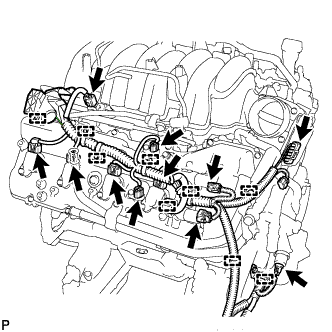
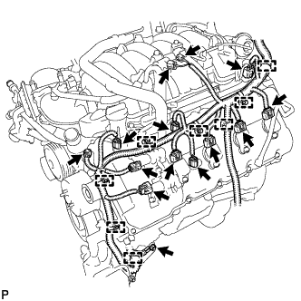
32. INSTALL ENGINE WIRE


A259652E01
  1. Install the engine wire.

  1. Engine Rear Side:

    1. Install the 3 wires with the 3 bolts.

      Torque:
      8.5 N*m{ 87 kgf*cm , 75 in.*lbf }

    2. Connect the 5 clamps.

    3. Connect the 3 connectors.


    A259650
  1. Engine RH Side:

    1. Connect the 9 clamps.

    2. Connect the oil pressure sender gauge connector.

    3. Connect the throttle sensor connector.

    4. Connect the fuel injector connector.

    5. Connect the 2 VVT sensor connectors.

    6. Connect the 4 ignition coil connectors.

    7. Connect the 2 camshaft timing control valve connectors.


    A259653
  1. Engine LH Side:

    1. Connect the 8 clamps and install the engine wire with the bolt.

      Torque:
      20 N*m{ 204 kgf*cm , 15 ft.*lbf }

    2. Connect the fuel injector connector.

    3. Connect the engine coolant temperature sensor connector.

    4. Connect the purge VSV connector.

    5. Connect the vacuum switching valve connector (for ACIS).

    6. Connect the camshaft position sensor connector.

    7. Connect the 2 VVT sensor connectors.

    8. Connect the 4 ignition coil connectors.

    9. Connect the 2 camshaft timing control valve connector.