Home › ENGINE ยท 1UR-FE › ENGINE MECHANICAL › ENGINE UNIT

ENGINE UNIT > REMOVAL

for Preparation Click here


1. REMOVE ENGINE WIRE


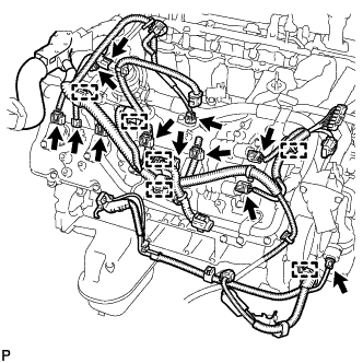
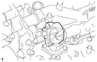
  1. Engine LH Side:


      A308815
    1. Disconnect the 2 camshaft timing control valve connectors.

    2. Disconnect the 4 ignition coil connectors.

    3. Disconnect the 2 VVT sensor connectors.

    4. Disconnect the camshaft position sensor connector.

    5. Disconnect the crankshaft position sensor connector.

    6. Disconnect the air switching valve connector.

    7. Disconnect the engine coolant temperature sensor connector.

    8. Disconnect the fuel injector connector.

    9. Disconnect the noise filter connector.

    10. Remove the bolt and disconnect the 8 clamps.
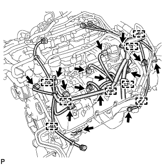


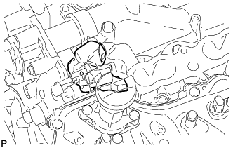
  1. Engine RH Side:


      A308816
    1. Disconnect the 2 camshaft timing control valve connectors.

    2. Disconnect the 4 ignition coil connectors.

    3. Disconnect the 2 VVT sensor connectors.

    4. Disconnect the fuel injector connector.

    5. Disconnect the noise filter connector.

    6. Disconnect the air switching valve connector.

    7. Disconnect the oil pressure sender gauge connector.

    8. Disconnect the 6 clamps.


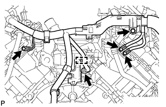
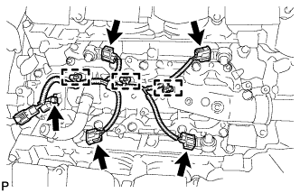
  1. Engine Rear Side:


      A214588
    1. Disconnect the connector and clamp.

    2. Remove the 4 bolts.

  1. Remove the engine wire.


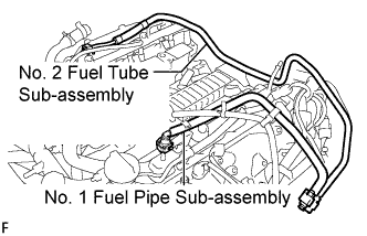
2. REMOVE NO. 1 FUEL PIPE SUB-ASSEMBLY


    A214592E02
  1. Remove the No. 1 fuel pipe (Click here).


3. REMOVE NO. 2 FUEL TUBE SUB-ASSEMBLY
  1. Remove the No. 2 fuel tube (Click here).


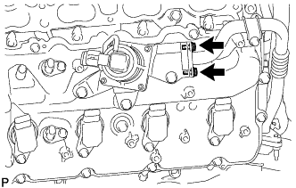
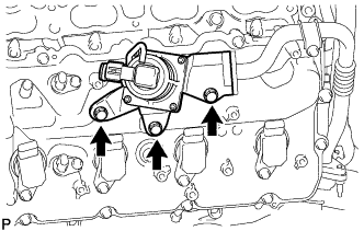
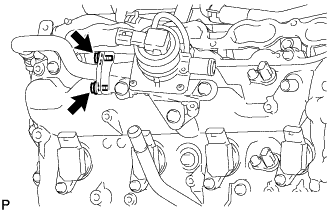
4. REMOVE AIR SWITCHING VALVE ASSEMBLY (for Bank 1)


    A308817
  1. Remove the 2 bolts.


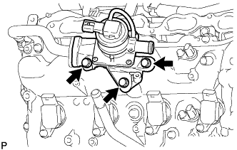
    A308818
  1. Remove the 3 bolts, air switching valve assembly and gasket.

    NOTICE:
    Be careful not to damage the installation surface of the gaskets.


5. REMOVE AIR SWITCHING VALVE ASSEMBLY (for Bank 2)


    A308819
  1. Remove the 2 bolts.


    A308820
  1. Remove the 3 bolts, air switching valve assembly and gasket.

    NOTICE:
    Be careful not to damage the installation surface of the gaskets.


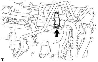
6. REMOVE NO. 4 AIR TUBE


    A214880
  1. Remove the bolt and wire harness clamp bracket.


    A214892
  1. Remove the bolt and No. 4 air tube.


7. REMOVE NO. 3 AIR TUBE


    A214881
  1. Remove the bolt and wire harness clamp bracket.


    A214893
  1. Remove the bolt and No. 3 air tube.


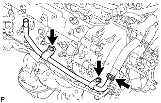
8. REMOVE NO. 3 WATER BY-PASS PIPE SUB-ASSEMBLY


    A214864
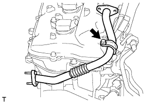
  1. Disconnect the hose and remove the 2 bolts and No. 3 water by-pass pipe.


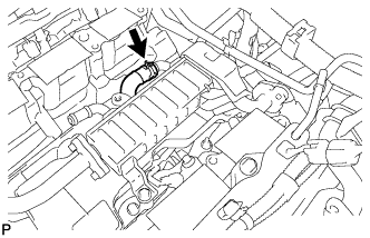
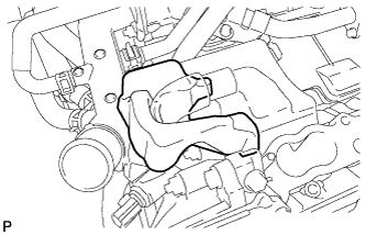
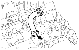
9. REMOVE NO. 8 WATER BY-PASS HOSE


    A308821
  1. Remove the No. 8 water by-pass hose.


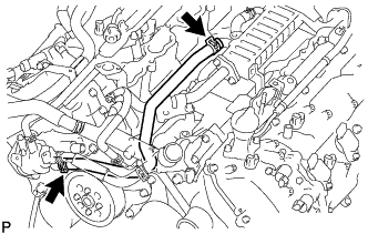
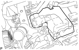
10. DISCONNECT NO. 11 WATER BY-PASS HOSE


    A214292
  1. Disconnect the No. 11 water by-pass hose.


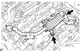
11. REMOVE EGR COOLER ASSEMBLY


    A214294
  1. Remove the 2 bolts and EGR cooler.


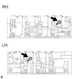
12. REMOVE CYLINDER BLOCK WATER DRAIN COCK SUB-ASSEMBLY


A163838E01
  1. Remove the 2 water drain cock plugs from the water drain cocks.

  1. Remove the 2 water drain cocks from the cylinder block.


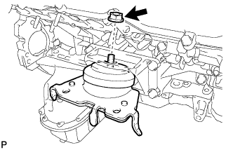
13. REMOVE FRONT ENGINE MOUNTING INSULATOR RH


    A214807
  1. Remove the nut and mounting insulator.


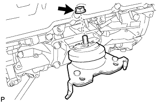
14. REMOVE FRONT ENGINE MOUNTING INSULATOR LH


    A214808
  1. Remove the nut and mounting insulator.


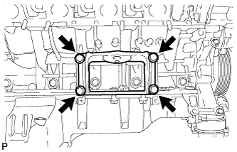
15. REMOVE FRONT NO. 1 ENGINE MOUNTING BRACKET RH


A214593
  1. Remove the 4 bolts and mounting bracket.


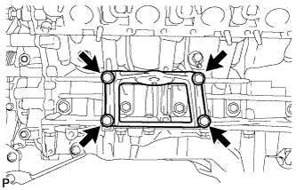
16. REMOVE FRONT NO. 1 ENGINE MOUNTING BRACKET LH


A214594
  1. Remove the 4 bolts and mounting bracket.


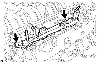
17. REMOVE FUEL DELIVERY PIPE SUB-ASSEMBLY LH
  1. Disconnect the No. 7 wire harness connector.


    A214316
  1. Remove the 2 bolts and fuel delivery pipe sub-assembly LH.

    NOTICE:
    When removing the fuel delivery pipe sub-assembly LH, hold the pipe by both ends and pull it straight upward.

  1. Remove the 2 delivery pipe spacers and 4 insulators from the cylinder head sub-assembly LH.


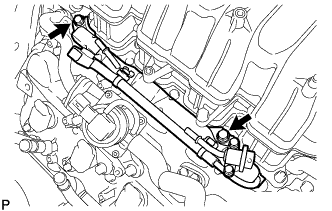
18. REMOVE FUEL DELIVERY PIPE SUB-ASSEMBLY RH
  1. Disconnect the No. 6 wire harness connector.


    A308874
  1. Remove the 2 bolts and fuel delivery pipe sub-assembly RH.

    NOTICE:
    When removing the fuel delivery pipe sub-assembly RH, hold the pipe by both ends and pull it straight upward.

  1. Remove the 2 delivery pipe spacers and 4 insulators from the cylinder head sub-assembly RH.


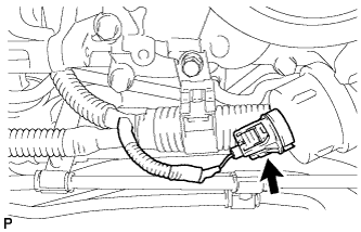
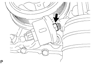
19. REMOVE OIL PRESSURE SENDER GAUGE ASSEMBLY


    A163657
  1. Disconnect the sender gauge connector.


    A162467
  1. Remove the oil pressure sender gauge.


20. REMOVE NO. 4 ENGINE COVER


    A214270
  1. Remove the No. 4 engine cover.


21. REMOVE NO. 3 ENGINE COVER


    A309475
  1. Remove the No. 3 engine cover.


22. REMOVE NO. 1 WATER BY-PASS HOSE


    A215865
  1. Remove the No. 1 water by-pass hose.


23. REMOVE AIR TUBE SUB-ASSEMBLY RH


    A210014
  1. Remove the 2 bolts and air tube sub-assembly RH from the cylinder head cover sub-assembly RH.


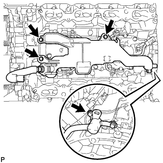
24. REMOVE WATER BY-PASS PIPE SUB-ASSEMBLY


    A210015
  1. Slide the clamp and disconnect the No. 2 water by-pass hose from the water by-pass pipe sub-assembly.

  1. Remove the 2 bolts and water by-pass pipe sub-assembly from the cylinder head cover sub-assembly RH.


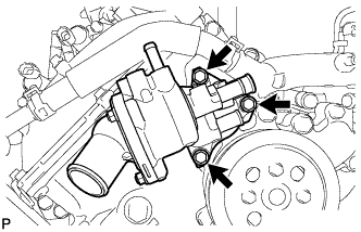
25. REMOVE WATER INLET HOUSING


    A210016
  1. Remove the 3 bolts, water inlet housing and gasket from the timing chain cover sub-assembly.


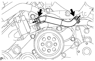
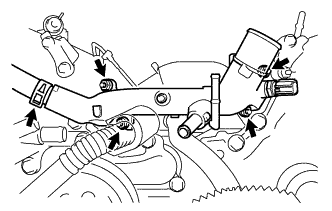
26. REMOVE FRONT WATER BY-PASS JOINT


    A308524
  1. Slide the clamp and remove the No. 2 water by-pass hose from the front water by-pass joint.

  1. Remove the 4 nuts, front water by-pass joint and 2 gaskets from the cylinder head.


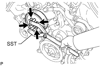
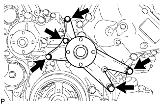
27. REMOVE WATER PUMP PULLEY


    A210018E02
  1. Using SST, hold the water pump pulley.

    SST
    09960-10010   (09962-01000, 09963-01000)

  1. Remove the 4 bolts and water pump pulley.


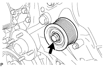
28. REMOVE NO. 1 IDLER PULLEY SUB-ASSEMBLY


    A210019
  1. Remove the bolt and No. 1 idler pulley sub-assembly from the timing chain cover sub-assembly.


29. REMOVE FAN BRACKET SUB-ASSEMBLY


    A210020
  1. Remove the 5 bolts and fan bracket assembly from the timing chain cover sub-assembly.


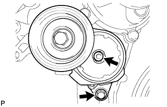
30. REMOVE V-RIBBED BELT TENSIONER ASSEMBLY


    A162527
  1. Remove the bolt, 6 mm hexagon bolt and V-ribbed belt tensioner assembly from the timing chain cover sub-assembly.


31. REMOVE SEPARATOR CASE


    A272394
  1. Remove the 4 bolts and separator case.


32. REMOVE NO. 2 ENGINE COVER


    A214852
  1. Remove the No. 2 engine cover.


33. REMOVE NO. 1 ENGINE COVER


    A308822
  1. Remove the No. 1 engine cover.


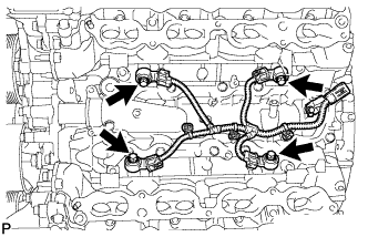
34. REMOVE ENGINE WIRE


A214595
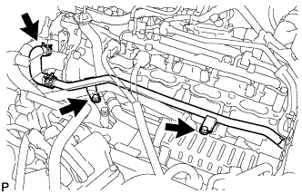
  1. Disconnect the 4 knock sensor connectors.

  1. Disconnect the 3 clamps. Then remove the engine wire.


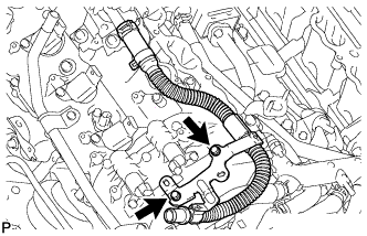
35. REMOVE NO. 11 WATER BY-PASS HOSE


    A214627
  1. Remove the No. 11 water by-pass hose.


36. REMOVE KNOCK SENSOR


    A215436
  1. Disconnect the 4 knock sensor connectors.

  1. Remove the 4 bolts and 4 knock sensors.


37. REMOVE IGNITION COIL ASSEMBLY
  1. Remove the 8 bolts and 8 ignition coils.


38. REMOVE NOISE FILTER
  1. LH Side:
    Remove the bolt and noise filter from the cylinder head cover.

  1. RH Side:
    Remove the bolt and noise filter from the cylinder head cover.