 |
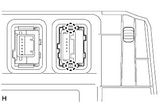
Attach the 2 claws to install the back sonar or clearance sonar switch assembly.
CLEARANCE SONAR MAIN SWITCH > INSTALLATION |
| 1. INSTALL BACK SONAR OR CLEARANCE SONAR SWITCH ASSEMBLY |
|
Attach the 2 claws to install the back sonar or clearance sonar switch assembly.
| 2. INSTALL NO. 2 SWITCH HOLE BASE |
Connect each connector.
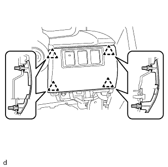 |
Attach the 4 clips to install the No. 2 switch hole base.
| 3. INSTALL LOWER INSTRUMENT PANEL FINISH PANEL SUB-ASSEMBLY LH |
Connect the hood lock control cable to the hood lock control lever, rotate the hood lock control cable, and then slide and push the hood lock control cable into place.
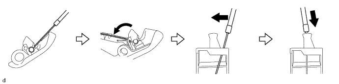
Attach the 3 hooks to connect the hood lock control lever to the lower instrument panel finish panel sub-assembly LH.
Connect each connector.
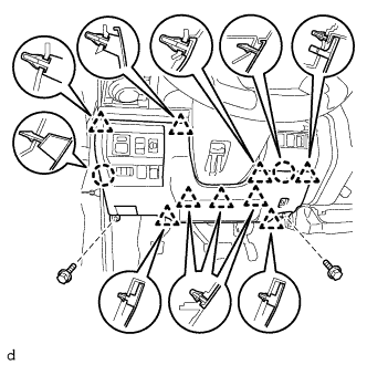 |
Attach the 9 clips and 2 claws to install the lower instrument panel finish panel sub-assembly LH.
Install the 2 bolts <A>.
| 4. INSTALL COWL SIDE TRIM BOARD LH |
Attach the 2 clips to install the cowl side trim board LH.
Install the nut.
| 5. INSTALL FRONT DOOR SCUFF PLATE LH |
Attach the 6 claws and 3 clips to install the front door scuff plate LH.
| 6. INSTALL INSTRUMENT SIDE PANEL LH |
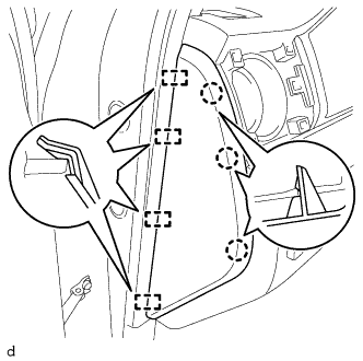 |
Attach the 4 guides and 3 claws to install the instrument side panel LH.