Measure the resistance according to the value(s) in the table below.
Connect the connectors to the vehicle side wire harnesses, operate the motor, and then measure the resistance at each position.
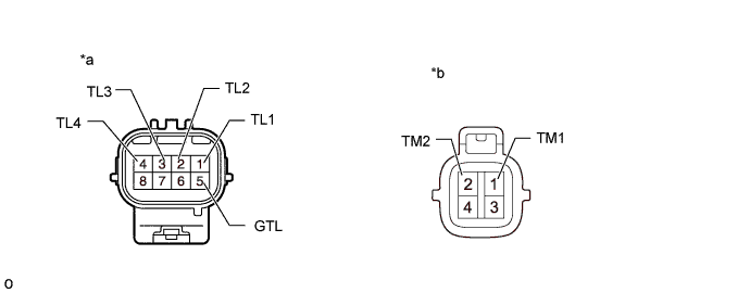
- Standard Resistance:
Tester Connection Condition Specified Condition 1 (TL1) - 5 (GTL) 2WD Below 1 Ω 2 (TL2) - 5 (GTL) Below 1 Ω 3 (TL3) - 5 (GTL) 10 kΩ or higher 4 (TL4) - 5 (GTL) Below 1 Ω 1 (TM1) - 2 (TM2) 0.47 to 0.87 Ω 1 (TL1) - 5 (GTL) 4HI 10 kΩ or higher 2 (TL2) - 5 (GTL) Below 1 Ω 3(TL3) - 5(GTL) Below 1 Ω 4 (TL4) - 5 (GTL) 10 kΩ or higher 1 (TM1) - 2 (TM2) 0.47 to 0.87 Ω 1 (TL1) - 5 (GTL) 4LO Below 1 Ω 2(TL2) - 5(GTL) 10 kΩ or higher 3 (TL3) - 5 (GTL) Below 1 Ω 4 (TL4) - 5 (GTL) 10 kΩ or higher 1 (TM1) - 2 (TM2) 0.47 to 0.87 Ω
Text in Illustration *a Component without harness connected
(Transfer Shift Actuator Assembly (Limit Switch))*b Component without harness connected
(Transfer Shift Actuator Assembly (Transfer Shift Motor))