BODY PANEL ROOF PANEL ASSEMBLY REPLACEMENT
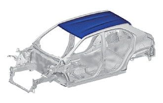
REMOVAL
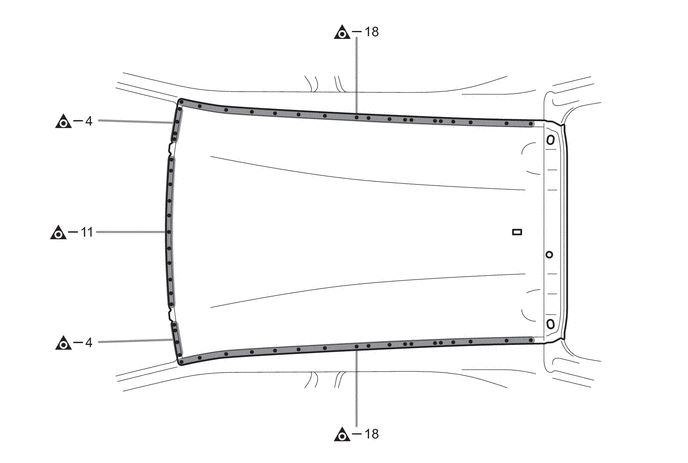
| Symbol Meaning | |
|---|---|

|
Remove Weld Points |

|
Remove Weld Points |
INSTALLATION
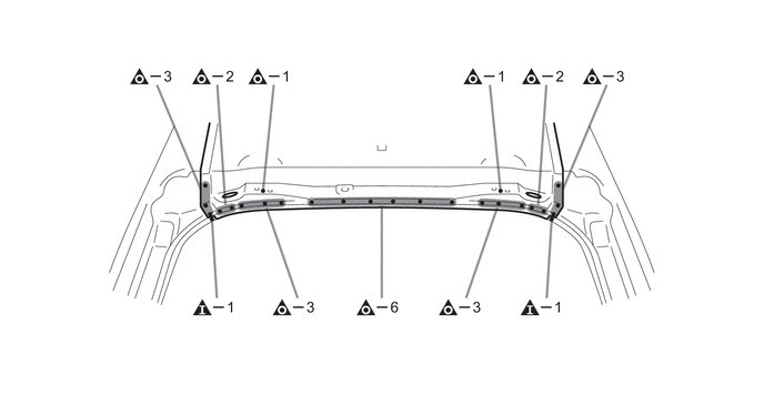
| Symbol Meaning | |
|---|---|

|
Spot Weld |

|
Plug Weld |

|
Plug Weld |

|
Body Sealer |
Inspect the fitting of the related parts around the new parts before welding. This affects the appearance of the finish.
Temporarily install the new parts and measure each part of the new parts in accordance with the body dimension diagram. (See the body dimensions)
Before temporarily installing the new parts, apply body sealer to the roof panel reinforcement, roof panel reinforcement no.2, roof panel reinforcement no.3, roof panel reinforcement no.4 and roof panel reinforcement no.7.
- HINT:
-
Apply enough body sealer to the panels.
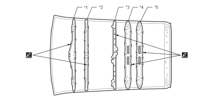
| *1 | ROOF PANEL REINFORCEMENT | *2 | ROOF PANEL REINFORCEMENT NO.2 |
| *3 | ROOF PANEL REINFORCEMENT NO.3 | *4 | ROOF PANEL REINFORCEMENT NO.4 |
| *5 | ROOF PANEL REINFORCEMENT NO.7 | - | - |
Before temporarily installing the new parts, weld the roof panel, roof panel reinforcement, roof panel reinforcement no.2, roof panel reinforcement no.3, roof panel reinforcement no.4 and roof panel reinforcement no.7 with the standard number of welding points.
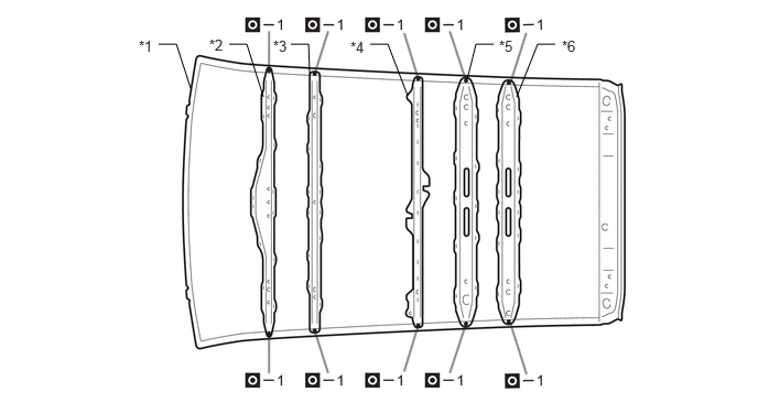
| *1 | ROOF PANEL | *2 | ROOF PANEL REINFORCEMENT |
| *3 | ROOF PANEL REINFORCEMENT NO.2 | *4 | ROOF PANEL REINFORCEMENT NO.3 |
| *5 | ROOF PANEL REINFORCEMENT NO.4 | *6 | ROOF PANEL REINFORCEMENT NO.7 |
Before temporarily installing the new parts, apply body sealer to the windshield header panel sub-assembly, roof panel reinforcement center and back door opening frame sub-assembly.
- HINT:
-
Apply enough body sealer to the panels.
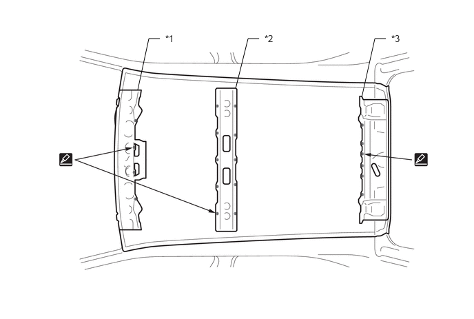
| *1 | WINDSHIELD HEADER PANEL SUB-ASSEMBLY | *2 | ROOF PANEL REINFORCEMENT CENTER |
| *3 | BACK DOOR OPENING FRAME SUB-ASSEMBLY | - | - |
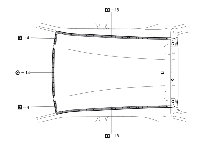
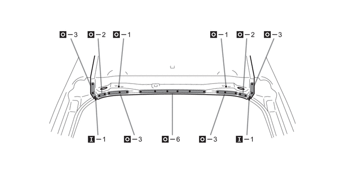
After welding, apply the foamed sealing material to the corresponding parts. (See the painting /coating)
After welding, apply body sealer to the corresponding parts. (See the painting /coating)
After applying the top coat, apply anti-rust agent to the internal panel portion of the closed section structural weld points.
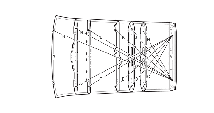
- Reference Value:
Area Measurement Area Measurement A 600 mm (23.62 in.) B 700 mm (27.56 in.) C 784 mm (30.87 in.) D 873 mm (34.37 in.) E 1019 mm (40.12 in.) F 1307 mm (51.46 in.) G 1458 mm (57.40 in.) H 763 mm (30.04 in.) J 885 mm (34.84 in.) K 1016 mm (40.00 in.) L 1304 mm (51.34 in.) M 1465 mm (57.68 in.) N 1723 mm (67.83 in.) - -