BODY PANEL REAR FLOOR PAN(for AWD) ASSEMBLY REPLACEMENT
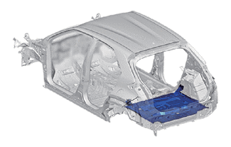
With the body lower back panel assembly removed.
REMOVAL
| Symbol Meaning | |
|---|---|

|
Remove Weld Points |

|
Cut with Disc Sander etc. |
Remove the center floor panel reinforcement sub-ssembly.
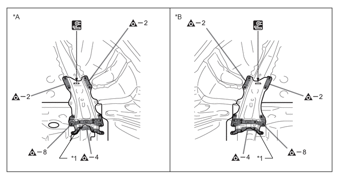
| *A | LH Side | *B | RH Side |
| *1 | CENTER FLOOR PANEL REINFORCEMENT SUB-ASSEMBLY | - | - |
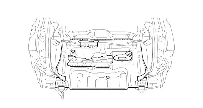
Roughly cut open the panel so that the adhesive can be reached. Cut through the adhesive with a cut chisel to remove the panel.
- HINT:
-
In cases where the adhesive cannot be removed with a cut chisel, heat the adhesive with an industrial heater gun or gas burner taking care not to cause panel deformation by overheating.

|
Adhesive | - | - |
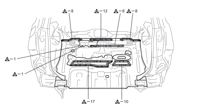
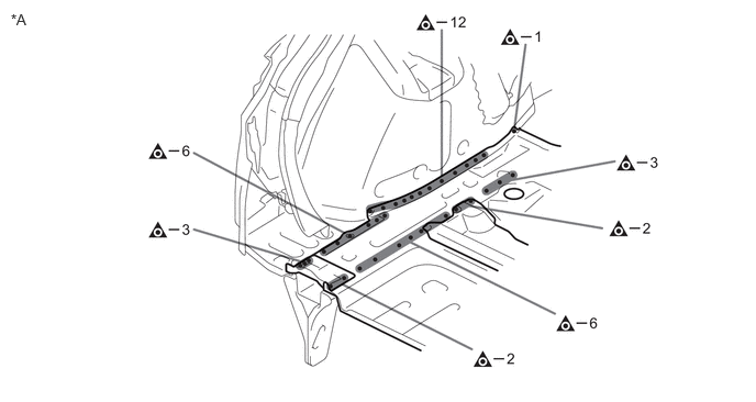
| *A | LH Side | - | - |
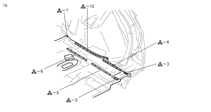
| *A | RH Side | - | - |
INSTALLATION
| Symbol Meaning | |
|---|---|

|
Plug Weld |

|
Fillet Weld |
Before temporarily installing the new parts, weld the rear floor pan, voltage converter mount bracket lower front, voltage converter mount bracket upper rear, voltage converter mount bracket lower rear, rear floor side panel, voltage converter mount bracket upper front and with the standard number of welding points.
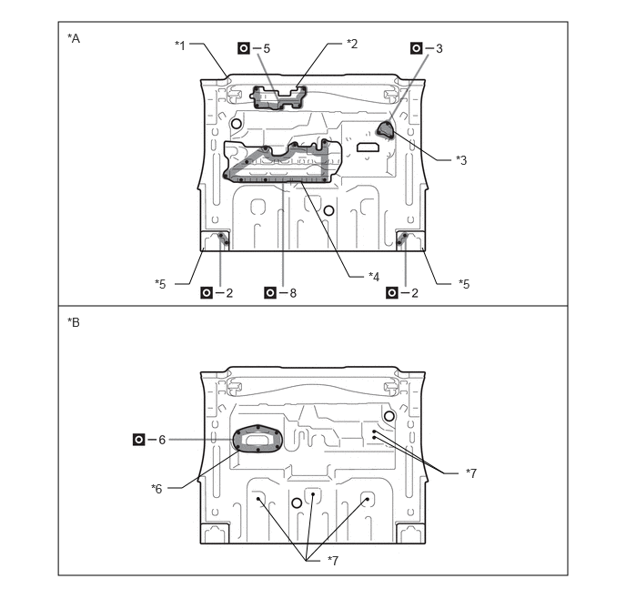
| *A | Upper Face | *B | Lower Face |
| *1 | REAR FLOOR PAN | *2 | VOLTAGE CONVERTER MOUNT BRACKET LOWER FRONT |
| *3 | VOLTAGE CONVERTER MOUNT BRACKET UPPER REAR | *4 | VOLTAGE CONVERTER MOUNT BRACKET LOWER REAR |
| *5 | REAR FLOOR SIDE PANEL | *6 | VOLTAGE CONVERTER MOUNT BRACKET UPPER FRONT |
| *7 | WELD BOLTS | - | - |
Apply adhesive (3MTM AutomixTM Panel Bonding Adhesive #8115).
- HINT:
- ·
Do not apply adhesive around the plug welding points.
·Minimize squeeze out in plug welding areas.
|
|
Adhesive | - | - |
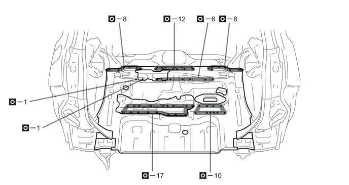
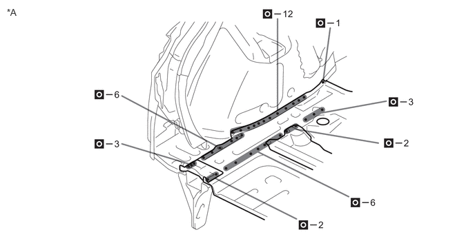
| *A | LH Side | - | - |
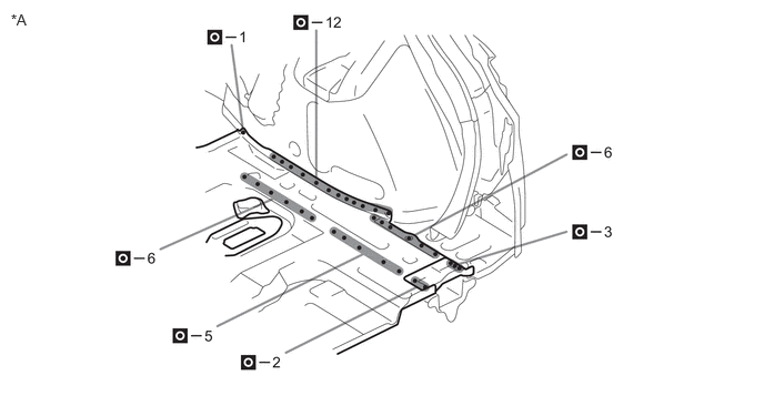
| *A | RH Side | - | - |
Weld the wheelhouse inner gusset front to the vehicle side.
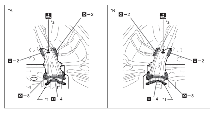
| *A | LH Side | *B | RH Side |
| *1 | CENTER FLOOR PANEL REINFORCEMENT SUB-ASSEMBLY | - | - |
| *a | 15 mm (0.59 in.) | - | - |
After welding, apply body sealer and undercoating to the corresponding parts. (See the painting /coating)
After applying the top coat, apply anti-rust agent to the internal panel portion of the closed section structural weld points.