NM3700E
_58
Vehicle Interior
_094254
HEATING / AIR CONDITIONING
_0443877
AIR CONDITIONING SYSTEM
DE
DETAILS
F
HEATING / AIR CONDITIONING AIR CONDITIONING SYSTEM DETAILS AIR CONDITIONING UNIT
CONSTRUCTION
a.
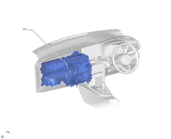
A semi-center location air conditioning radiator assembly, in which the evaporator and heater radiator unit sub-assembly are placed in the vehicle's longitudinal direction, is used. As a result, the air conditioning radiator assembly has been made compact and lightweight.
b.
A compact wide-angle high flow defroster that gives the defroster nozzle assembly inner wall a radial shape is used to ensure superior defroster performance.
Air Conditioning Unit Layout Parts Location
2.583,2.5 1.333,1.25
1.333,1.25 1.167,1.25
true
0.979,1.167 1.292,1.365
0.313,0.198
10
false
*1
0.271,5.469 0.583,5.667
0.313,0.198
10
false
*a
| *1 | Air Conditioning Unit Assembly | - | - |
| *a | The illustration shown is an example only. | - | - |
Duct Layout Parts Location
2.656,2.042 2.219,1.073
2.219,1.073 2.052,1.073
true
5.01,2.042 5.49,1.125
5.49,1.125 5.656,1.125
true
1.823,2.906 1.083,1.333
1.083,1.333 0.917,1.333
true
3.302,2.927 4,0.667
4,0.667 4.167,0.667
true
0.615,5.198 0.781,5.198
0.781,5.198 2.167,3.958
true
1.375,3.01 0.667,2.26
0.667,2.26 0.5,2.26
true
4.229,3.333 5.573,3.75
5.573,3.75 5.74,3.75
true
5.271,2.313 5.875,1.969
5.875,1.969 6.042,1.969
true
4.219,0.583 4.531,0.74
0.313,0.156
10
false
*1
1.844,0.958 2.156,1.115
0.313,0.156
10
false
*2
0.719,1.229 1.031,1.385
0.313,0.156
10
false
*3
0.281,2.146 0.594,2.302
0.313,0.156
10
false
*4
0.396,5.094 0.708,5.25
0.313,0.156
10
false
*5
5.802,3.635 6.115,3.792
0.313,0.156
10
false
*6
0.25,6.552 0.563,6.708
0.313,0.156
10
false
*a
6.094,1.885 6.406,2.042
0.313,0.156
10
false
*7
5.708,1.042 6.021,1.198
0.313,0.156
10
false
*8
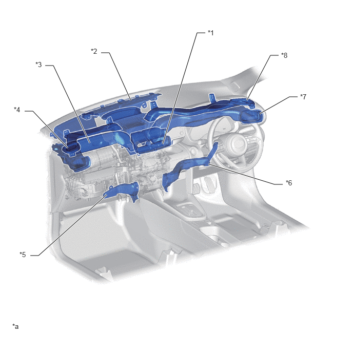
| *1 | Center Register Duct | *2 | Front Defroster Duct |
| *3 | Front Passenger Side Register Duct | *4 | Front Passenger Side Defroster Duct |
| *5 | Front Passenger Side Footwell Duct | *6 | Driver Side Footwell Duct |
| *7 | Driver Side Register Duct | *8 | Driver Side Defroster Duct |
| *a | The illustration shown is an example only. | - | - |
OPERATION
a.
Mode Position and Damper Operation
4.74,1.76 5.365,0.99
5.365,0.99 5.531,0.99
true
3.135,2.865 2.729,3.823
2.729,3.823 2.563,3.823
true
5.375,2.125 5.813,2.333
5.813,2.333 5.979,2.333
true
4.635,2.813 4.927,3.885
4.927,3.885 5.094,3.885
true
3.24,1.906 2.958,1.302
2.958,1.302 2.792,1.302
true
2.667,2.865 2.323,3.458
2.323,3.458 2.156,3.458
true
1.01,1.719 0.75,2.146
0.75,2.146 0.583,2.146
true
1.094,2.656 0.865,3.208
0.865,3.208 0.698,3.208
true
0.396,2.052 0.708,2.208
0.313,0.156
10
false
*1
0.521,3.104 0.833,3.26
0.313,0.156
10
false
*2
1.969,3.344 2.281,3.5
0.313,0.156
10
false
*3
2.385,3.729 2.698,3.885
0.313,0.156
10
false
*4
3.188,3.635 3.5,3.792
0.313,0.156
10
false
*5
4.26,3.646 4.573,3.802
0.313,0.156
10
false
*6
5.302,3.625 5.615,3.781
0.313,0.156
10
false
*7
5.594,0.885 5.906,1.042
0.313,0.156
10
false
*8
5.615,2.583 5.927,2.74
0.313,0.156
10
false
*9
5.615,1.771 6.083,1.927
0.469,0.156
10
false
*10
4.521,0.406 4.99,0.563
0.469,0.156
10
false
*11
5.74,0.604 6.208,0.76
0.469,0.156
10
false
*12
3.354,0.604 3.823,0.76
0.469,0.156
10
false
*13
2.552,1.198 3.021,1.354
0.469,0.156
10
false
*14
0.198,4.479 0.51,4.635
0.313,0.156
10
false
*a
4.896,1.594 5.208,1.75
0.313,0.156
10
false
J
5.042,1.844 5.354,2
0.313,0.156
10
false
I
4.948,2.01 5.26,2.167
0.313,0.156
10
false
H
4.771,2.115 5.083,2.271
0.313,0.156
10
false
G
6.021,2.25 6.333,2.406
0.313,0.156
10
false
*8
5.146,2.542 5.458,2.698
0.313,0.156
10
false
E
4.99,2.458 5.302,2.615
0.313,0.156
10
false
F
4.677,2.302 4.99,2.458
0.313,0.156
10
false
I
4.479,2.167 4.792,2.323
0.313,0.156
10
false
J
3.792,2.635 4.104,2.792
0.313,0.156
10
false
G
3.771,3 4.083,3.156
0.313,0.156
10
false
H
5.146,3.802 5.458,3.958
0.313,0.156
10
false
*8
3.438,2.667 3.75,2.823
0.313,0.156
10
false
D
2.99,1.917 3.302,2.073
0.313,0.156
10
false
C
1.698,1.51 2.01,1.667
0.313,0.156
10
false
A
0.906,1.5 1.219,1.656
0.313,0.156
10
false
B
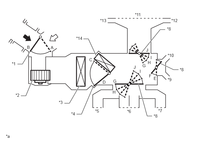
| *1 | Air Inlet Control Damper | *2 | Blower Motor with Fan Sub-assembly |
| *3 | No. 1 Cooler Evaporator Sub-assembly | *4 | Air Mix Control Damper |
| *5 | Passenger Side Register | *6 | Center Register |
| *7 | Driver Side Register | *8 | Mode Switching Damper |
| *9 | Front Passenger Side Footwell Register | *10 | Front Driver Side Footwell Register |
| *11 | Front Defroster | *12 | Driver Side Defroster |
| *13 | Front Passenger Side Defroster | *14 | Heater Radiator Unit Sub-assembly |
| *a | This illustration is a diagram of the servo motor position in each mode. The actual position of parts and number of servo motors may vary from the actual vehicle. | - | - |

|
Fresh Air | 
|
Recirculated Air |
| Control Damper | Operation Position | Damper Position | Operation |
|---|---|---|---|
| Air Inlet Control Damper | FRESH | A | Allows fresh air to enter. |
| RECIRCULATION | B | Causes internal air to recirculate. | |
| Air Mix Control Damper | LO - HI | C - D | Varies the mixture ratio of cool air and hot air in order to regulate the temperature continuously from Cool to Hot. |
| Air Outlet Control Damper | DEF

|
E, J | Defrosts the windshield through the center defroster, side defrosters and side registers. |
FOOT/DEF

|
F, J | Defrosts the windshield through the center defroster and side defrosters, while air is also blown out from the front footwell register ducts. In addition, air blows out slightly from the side registers. | |
FOOT

|
F, I | Air blows out of the front footwell register ducts. In addition, air blows out slightly from the center defroster, side defrosters, side registers. | |
B/L

|
F, H | Air blows out of the center registers, side registers and front and rear footwell register ducts. | |
FACE

|
E, G | Air blows out of the center registers and side registers. |
b.
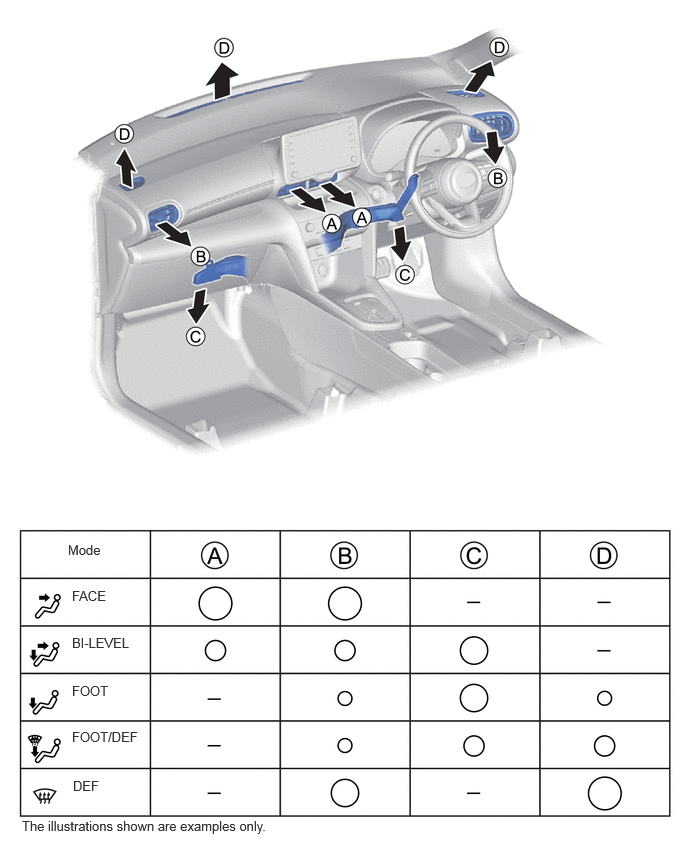
Air Outlets and Airflow Volume
0.708,5.646 1.323,5.844
0.615,0.198
10
false
Mode
0.75,6.125 1.365,6.323
0.615,0.198
10
false
FACE
0.75,6.615 1.521,6.865
0.771,0.25
10
false
BI-LEVEL
0.75,7.115 1.365,7.313
0.615,0.198
10
false
FOOT
0.75,7.594 1.531,7.802
0.781,0.208
10
false
FOOT/DEF
0.76,8.104 1.375,8.302
0.615,0.198
10
false
DEF
0.229,8.521 3.583,8.75
3.354,0.229
10
false
The illustrations shown are examples only.
- HINT:
-
The size of the circle ○ indicates the proportion of airflow volume.