EXTERIOR PANELS / TRIM BODY STRUCTURE DETAILS BODY SHELL
CONSTRUCTION
Body Shell
By optimizing the layout of the body frame members, optimizing the joining method and configuring reinforcing material, the body structure is lightweight and highly rigid, enhancing excellent handling stability.
The closed cross-section construction of the suspension tower brace and outer cowl top panel sub-assembly main body provides enhanced rigidity of frame connections, helps providing excellent handling stability.
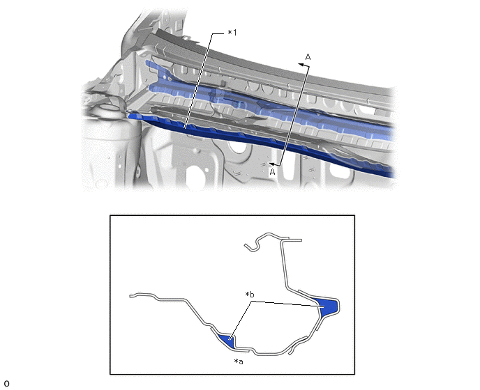
| *1 | Outer Cowl Top Panel Sub-assembly | - | - |
| *a | A - A Cross Section | *b | Closed Cross-sections |
The flat ring shape of the closed cross-section portions of the instrument panel reinforcement assembly and outer cowl top panel sub-assembly provide excellent steering rigidity.
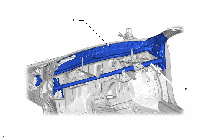
| *1 | Outer Cowl Top Panel Sub-assembly | *2 | Instrument Panel Reinforcement Assembly |
Side Body
The side member outer reinforcement is rigidly connected and forms an annular structure, enhancing the rigidity of the body frame joints.
The frame joining was enhanced by adding top plate surface spot welds and flange spot welds to the front body pillar and rail.
By increasing the number of spot welds, including spot welds from an overhead view, the joining rigidity of the frame was enhanced.
The width of the lower joint of each pillar was expanded in the front-back direction.
By increasing the number of spot welds, including the spot welds in planar view, the joining rigidity of the frame was enhanced.
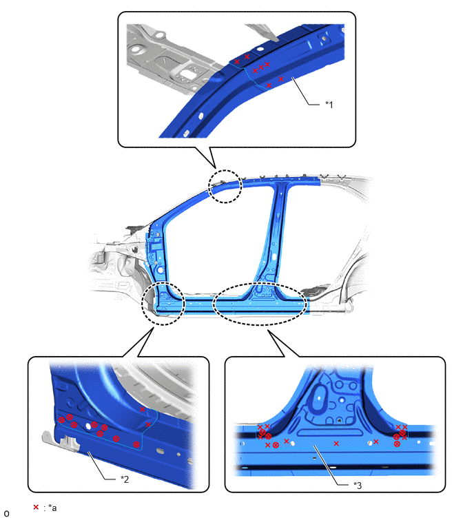
| *1 | Roof Side Rail | *2 | Rocker Panel |
| *3 | Center Body Pillar | - | - |
| *a | Bond Dot | - | - |
Ring Structure
The rear body uses an annular structure comprising the No. 2 rear floor cross member and quarter wheel house inner panel sub-assemblies to ensure excellent torsional rigidity.
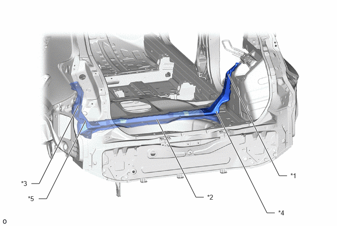
| *1 | Quarter Wheel House Inner Panel Sub-assembly RH | *2 | No. 2 Rear Floor Cross Member |
| *3 | Quarter Wheel House Inner Panel Sub-assembly LH | *4 | Wheel House Inner Gusset RH |
| *5 | Wheel House Inner Gusset LH | - | - |
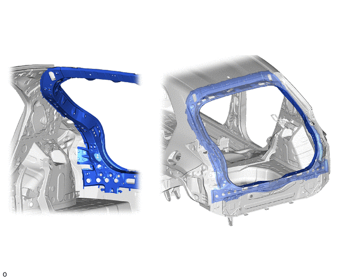
Excellent torsional rigidity is enhanced by connecting the reinforcements at the back door opening with ridge lines to form an annular structure.
High-rigidity Urethane Sealant
Body rigidity is achieved by using a high-rigidity urethane sealant for bonding windshield glass.
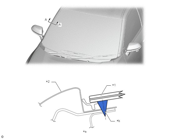
| *1 | Windshield Glass | *2 | Front Body Side Panel |
| *a | A - A Cross Section | *b | High-rigidity Urethane Sealant |
Front Side Member Reinforcement RR
The torsional rigidity and steering stability of the body have been enhanced by increasing the lap amount of the frame member to enhance the bond formation.
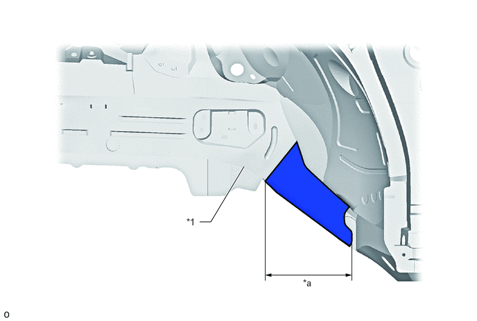
| *1 | Front Side Member Reinforcement RR | - | - |
| *a | Lap | - | - |
Center Floor Cross Member Sub-assembly
By increasing the height of the rear end of the tunnel and combining it with the center floor cross member sub-assembly, the body rigidity and steering stability were enhanced.
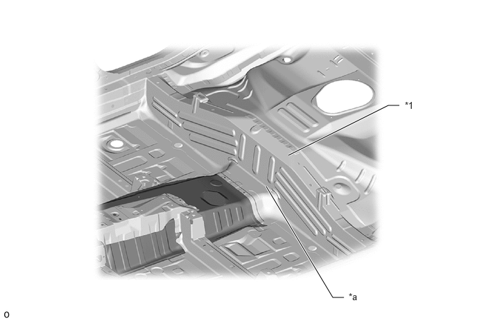
| *1 | Center Floor Cross Member Sub-assembly | - | - |
| *a | Tunnel Rear End | - | - |
Rear Side Member Sub-assembly
By changing the way the rear side member sub-assembly is combined with the rocker panel and center floor cross member sub-assembly, the torsional rigidity and handling stability of the body are enhanced by enhancing the coupling rigidity.
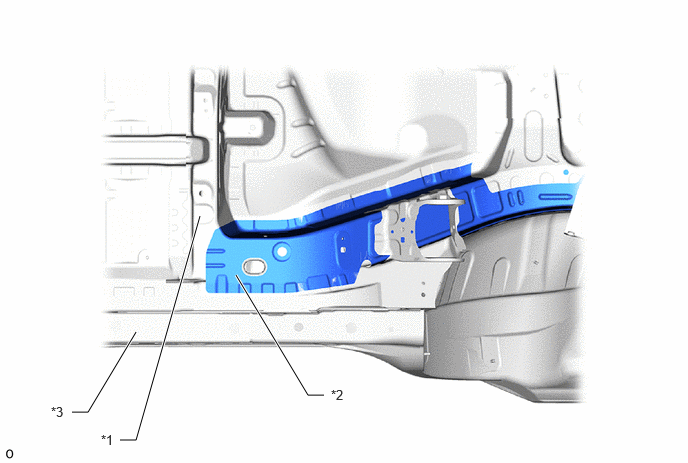
| *1 | Rocker Panel | *2 | Center Floor Cross Member Sub-assembly |
| *3 | Rear Side Member Sub-assembly | - | - |
Strainer
By adopting a strainer in the rear wheel house and suppressing the inward sag of the rear wheel house, the torsional rigidity and steering stability of the body were enhanced.
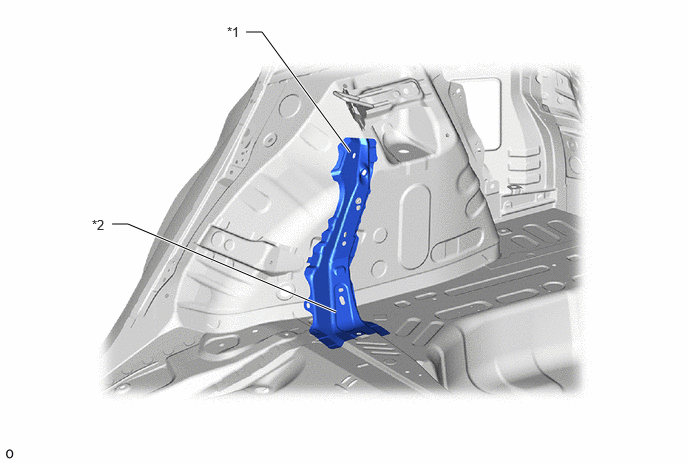
| *1 | Strainer | *2 | Wheel House Inner Gusset |
Structural Adhesive
By using structural adhesive over a wide range of areas such as the floor panels, side doors and back door opening, the joint rigidity between parts has been increased, and steering stability and ride comfort have been enhanced.
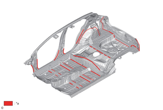
| *a | Structural Adhesive | - | - |