K320 MULTIDRIVE / CVT SHIFT STROKE SENSOR INSPECTION
PROCEDURE

 1.INSPECT SHIFT STROKE SENSOR
Pre-procedure1
Connect 3 new dry-cell batteries (1.5 V each) in series.
Prepare a magnet or equivalent tool.
Connect a positive (+) lead from the batteries to terminal 2 (VDD) and a negative (-) lead to terminal 3 (GND).
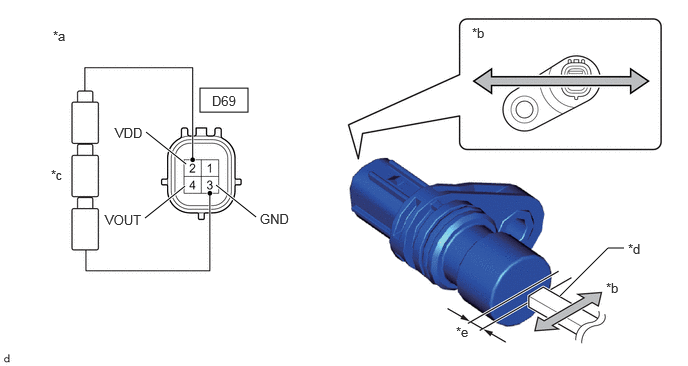
| *a | Component without harness connected
(Shift Stroke Sensor) |
*b | Magnet Movement Direction |
| *c | Dry Cell Battery | *d | Magnet |
| *e | 2.6 mm (0.102 in.) or less | - | - |
Wave the magnet left and right 2.6 mm (0.102 in.) or less from the tip of the shift stroke sensor to output a high/low signal while measuring the voltage.
Procedure1
Measure the voltage according to the value(s) in the table below.
- Standard Voltage (Combined Dry-cell Battery Voltage of 4.5 V):
Tester Connection Condition Specified Condition Click Location & Routing(D69)Location & Routingewd_type=routing;type=c;code=D69
Click Connector(D69)Engine Compartment>Engine Wire>Shift Stroke Sensorewd_type=component;type=c;code=D69;pinno=4,3
D69-4 (VOUT) - D69-3 (GND) High voltage 4.09 to 4.19 V D69-4 (VOUT) - D69-3 (GND) Low voltage 0.36 to 0.45 V
- Reference Voltage (Combined Dry-cell Battery Voltage of 5.0 V):
Tester Connection Condition Specified Condition Click Location & Routing(D69)Location & Routingewd_type=routing;type=c;code=D69
Click Connector(D69)Engine Compartment>Engine Wire>Shift Stroke Sensorewd_type=component;type=c;code=D69;pinno=4,3
D69-4 (VOUT) - D69-3 (GND) High voltage 4.55 to 4.65 V D69-4 (VOUT) - D69-3 (GND) Low voltage 0.4 to 0.5 V
Post-procedure1
None.