RM3700E
_58
Vehicle Interior
_093025
LIGHTING (INT)
_0438516
VANITY LIGHT SWITCH
G
LIGHTING (INT) VANITY LIGHT SWITCH INSPECTION
PROCEDURE

 74310
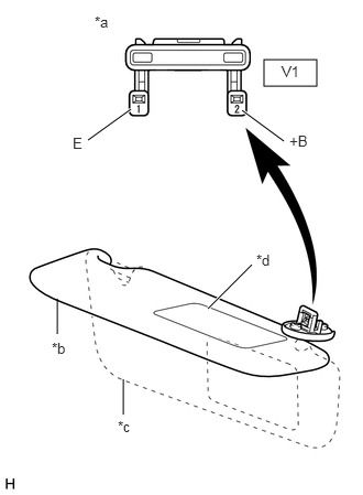
1.INSPECT VISOR ASSEMBLY RH
a.
Check the resistance.
i.
2.5,0.563 3,0.813
0.5,0.25
1.969,2.917 2.385,2.5
true
1.167,3.917 1.167,3.583
false
0.542,3.156 0.542,2.823
false
0.833,1.323 1.24,1.031
true
2.688,1.333 2.292,1.042
true
0.896,0.125 1.167,0.333
0.271,0.208
10
false
*a
0.49,3.208 0.76,3.417
0.271,0.208
10
false
*b
1.115,3.948 1.385,4.156
0.271,0.208
10
false
*c
2.427,2.375 2.698,2.583
0.271,0.208
10
false
*d
0.688,1.271 0.958,1.479
0.271,0.208
10
false
E
2.74,1.25 3.01,1.458
0.271,0.208
10
false
+B
2.667,0.594 2.938,0.802
0.271,0.208
10
false
V1
| *a | Component without harness connected
(Visor Assembly RH) |
| *b | Visor up |
| *c | Visor down |
| *d | Mirror Cover |
Measure the resistance according to the value(s) in the table below.
- Standard Resistance:
Tester Connection Condition Specified Condition Click Location & Routing(V1)Location & Routingewd_type=routing;type=c;code=V1
Click Connector(V1)Body>No. 1 Roof Wire>Visor Assembly RHewd_type=component;type=c;code=V1;pinno=2,1
V1-2 (+B) - V1-1 (E) Visor up 10 kΩ or higher V1-2 (+B) - V1-1 (E) Mirror cover fully closed with visor down 10 kΩ or higher V1-2 (+B) - V1-1 (E) Mirror cover fully open with visor down Below 1 Ω
ii.
If the result is not as specified, replace the visor assembly RH.
74320
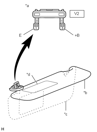
2.INSPECT VISOR ASSEMBLY LH
a.
Check the resistance.
i.
2.479,0.365 2.979,0.615
0.5,0.25
1.333,2.99 1.125,2.667
true
3,3.146 3,2.813
false
2.333,3.917 2.333,3.583
false
0.833,1.229 1.219,1
true
2.594,1.24 2.25,0.99
true
0.896,0.115 1.167,0.323
0.271,0.208
10
false
*a
2.958,3.198 3.229,3.406
0.271,0.208
10
false
*b
2.271,3.958 2.542,4.167
0.271,0.208
10
false
*c
0.938,2.552 1.208,2.76
0.271,0.208
10
false
*d
0.677,1.167 0.948,1.375
0.271,0.208
10
false
E
2.646,1.167 2.917,1.375
0.271,0.208
10
false
+B
2.635,0.396 2.906,0.604
0.271,0.208
10
false
V2
| *a | Component without harness connected
(Visor Assembly LH) |
| *b | Visor up |
| *c | Visor down |
| *d | Mirror Cover |
Measure the resistance according to the value(s) in the table below.
- Standard Resistance:
Tester Connection Condition Specified Condition Click Location & Routing(V2)Location & Routingewd_type=routing;type=c;code=V2
Click Connector(V2)Body>No. 1 Roof Wire>Visor Assembly LHewd_type=component;type=c;code=V2;pinno=2,1
V2-2 (+B) - V2-1 (E) Visor up 10 kΩ or higher V2-2 (+B) - V2-1 (E) Mirror cover fully closed with visor down 10 kΩ or higher V2-2 (+B) - V2-1 (E) Mirror cover fully open with visor down Below 1 Ω
ii.
If the result is not as specified, replace the visor assembly LH.