WIPER / WASHER WIPER AND WASHER SYSTEM Washer Motor Circuit
DESCRIPTION
When the windshield washer motor and pump assembly receives signals from the windshield wiper switch assembly, it operates to spray washer fluid from the washer nozzle sub-assemblies.
WIRING DIAGRAM
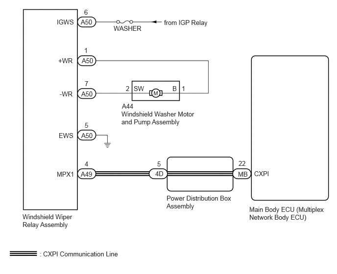
CAUTION / NOTICE / HINT
- NOTICE:
-
Inspect the fuses of circuits related to this system before performing the following procedure.
- HINT:
-
The wiper and washer system uses the CXPI communication system. First, confirm that there is no malfunction in the CXPI communication system.
PROCEDURE
Perform the Active Test according to the display on the GTS.
- Body Electrical > Main Body > Active Test
-
Tester Display Measurement Item Control Range Diagnostic Note Front Washer Relay Function to operate the windshield washer motor and pump assembly (Front) OFF or ON - Rear Washer Relay Function to operate the windshield washer motor and pump assembly (Rear) OFF or ON -
- Body Electrical > Main Body > Active Test
-
Tester Display Front Washer Relay - 50004 449 71
- Body Electrical > Main Body > Active Test
-
Tester Display Rear Washer Relay - 50004 449 76
- OK:
Windshield washer motor and pump assembly operates normally.
- Result:
Proceed to OK NG
OK
NG
OK
NG
Disconnect the A50 windshield wiper relay assembly connector.
Measure the voltage according to the value(s) in the table below.
- Standard Voltage:
Tester Connection Switch Condition Specified Condition Click Location & Routing(A50)Location & Routingewd_type=routing;type=c;code=A50
Click Connector(A50)Instrument Panel>Engine Room Main Wire>Windshield Wiper Relay Assemblyewd_type=component;type=c;code=A50;pinno=6
A50-6 (IGWS) - Body ground Ignition switch ON 11 to 14 V
- Result:
Proceed to OK NG
OK
NG
Measure the resistance according to the value(s) in the table below.
- Standard Resistance:
Tester Connection Condition Specified Condition Click Location & Routing(A50)Location & Routingewd_type=routing;type=c;code=A50
Click Connector(A50)Instrument Panel>Engine Room Main Wire>Windshield Wiper Relay Assemblyewd_type=component;type=c;code=A50;pinno=5
A50-5 (EWS) - Body ground Always Below 1 Ω
- Result:
Proceed to OK NG
OK
NG
Measure the resistance according to the value(s) in the table below.
- Standard Resistance:
Tester Connection Condition Specified Condition Click Location & Routing(A50,A44)Location & Routingewd_type=routing;type=c,c;code=A50,A44
Click Connector(A50)Instrument Panel>Engine Room Main Wire>Windshield Wiper Relay Assemblyewd_type=component;type=c;code=A50;pinno=1,7
Click Connector(A44)Engine Compartment>Engine Room Main Wire>Windshield Washer Motor and Pump Assemblyewd_type=component;type=c;code=A44;pinno=1,2
A50-1 (+WR) - A44-1 (B) Always Below 1 Ω A50-7 (-WR) - A44-2 (SW) Always Below 1 Ω A50-1 (+WR) or A44-1 (B) - Body ground Always 10 kΩ or higher A50-7 (-WR) or A44-2 (SW) - Body ground Always 10 kΩ or higher
- Result:
Proceed to OK NG
OK
NG