NAVIGATION / MULTI INFO DISPLAY NAVIGATION SYSTEM Data Signal Circuit between Radio Receiver and Stereo Jack Adapter
DESCRIPTION
The No. 1 stereo jack adapter assembly sends the sound data signal or image data signal from a USB device to the radio and display receiver assembly via this circuit.
WIRING DIAGRAM
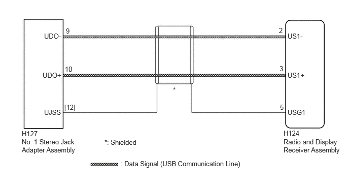
PROCEDURE
Disconnect the H124 radio and display receiver assembly connector.
Disconnect the H127 No. 1 stereo jack adapter assembly connector.
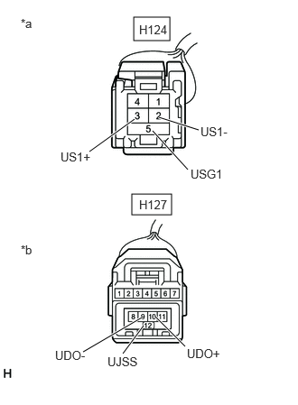
| *a | Front view of wire harness connector
(to Radio and Display Receiver Assembly) |
| *b | Front view of wire harness connector
(to No. 1 Stereo Jack Adapter Assembly) |
Measure the resistance according to the value(s) in the table below.
- Standard Resistance:
Tester Connection Condition Specified Condition Click Location & Routing(H124,H127)Location & Routingewd_type=routing;type=c,c;code=H124,H127
Click Connector(H124)Instrument Panel>Instrument Panel Wire / Speaker Wire>Radio & Display Receiver Assemblyewd_type=component;type=c;code=H124;pinno=2,3,5
Click Connector(H127)Instrument Panel>Instrument Panel Wire / Speaker Wire>No. 1 Stereo Jack Adapter Assemblyewd_type=component;type=c;code=H127;pinno=9,10
H124-2 (US1-) - H127-9 (UDO-) Always Below 1 Ω H124-3 (US1+) - H127-10 (UDO+) Always Below 1 Ω H124-5 (USG1) - H127-[12] (UJSS) Always Below 1 Ω H124-2 (US1-) or H127-9 (UDO-) - Body ground Always 10 kΩ or higher H124-3 (US1+) or H127-10 (UDO+) - Body ground Always 10 kΩ or higher H124-5 (USG1) or H127-[12] (UJSS) - Body ground Always 10 kΩ or higher
- Result:
Proceed to OK NG
OK
Click hereAudio / Visual / Telematics>NAVIGATION / MULTI INFO DISPLAY>NAVIGATION SYSTEM>PROBLEM SYMPTOMS TABLE
NG