THEFT DETERRENT / KEYLESS ENTRY IMMOBILISER SYSTEM(for HV Model without Entry and Start System) Power Source Mode does not Change to ON (READY)
DESCRIPTION
The key ID code of the transponder chip inside the IG key is compared against the key ID code registered in the transponder key ECU assembly. While checking the code, the transponder key ECU assembly supplies electrical power to the transponder chip in the key by means of the transponder key coil. If the codes match, the immobiliser is then UNSET (released), and after the hybrid control system start permission signal is sent to the hybrid vehicle control ECU assembly, if communication is functioning properly, hybrid control system start can be performed.
- HINT:
- ·
When the key is inserted into the ignition key cylinder, the transponder key coil receives the key code and outputs it to the transponder key ECU assembly.
·If this symptom occurs, there may be a communication problem between the transponder key coil and the transponder key ECU assembly.
WIRING DIAGRAM
Refer to "System Diagram".
CAUTION / NOTICE / HINT
- NOTICE:
- ·
When replacing the hybrid vehicle control ECU, key or transponder key ECU assembly, refer to Service Bulletin.
·Inspect the fuses for circuits related to this system before performing the following inspection procedure.
PROCEDURE
Clear the DTCs.
- Body Electrical > Immobiliser > Clear DTCs
- 50002 260
- Powertrain > Hybrid Control > Clear DTCs
- 50002 397
- Result:
Proceed to NEXT
NEXT
Check for DTCs.
- Body Electrical > Immobiliser > Trouble Codes
- 50001 260
- Powertrain > Hybrid Control > Trouble Codes
- 50001 397
- Result:
Proceed to OK NG
OK
NG
Read the Data List according to the display on the GTS.
- Powertrain > Hybrid Control > Data List
-
Tester Display Measurement Item Range Normal Condition Diagnostic Note Permit Start by Immobiliser Status of starting permission by immobiliser (immobiliser to hybrid vehicle ECU assembly) No Judgment / OK / NG - -
- Powertrain > Hybrid Control > Data List
-
Tester Display Permit Start by Immobiliser - 50003 397 213
- OK:
The item in the Data List indicates "Normal".
- Result:
Proceed to OK NG
OK
NG
Check that the security indicator light turns off when a registered key is inserted into the ignition key cylinder.
- OK:
Security indicator light turns OFF.
- Result:
Proceed to OK NG
OK
NG
Check that the security indicator light turns off when another registered key is inserted into the ignition key cylinder.
- OK:
Security indicator light turns OFF.
- Result:
Proceed to OK NG
OK
NG
Check that the hybrid control system start with another registered key.
- OK:
Hybrid control system starts normally.
- Result:
Proceed to OK NG
OK
NG
Using an oscilloscope, check the waveform.
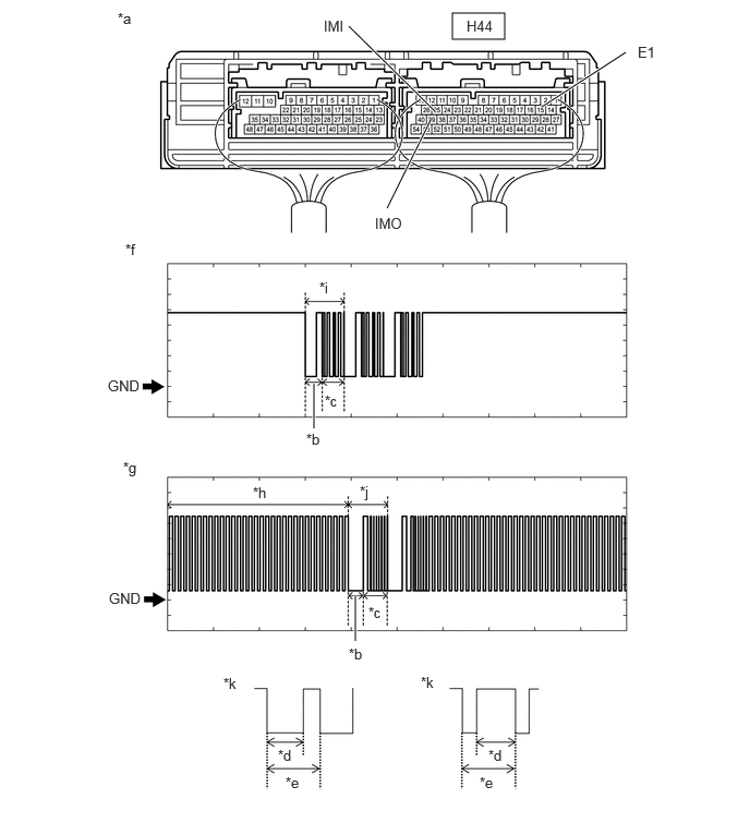
| *a | Component with harness connected
(Hybrid Vehicle ECU Assembly) |
*b | Approximately 160 ms |
| *c | Approximately 270 ms | *d | Approximately 40 ms |
| *e | Approximately 60 ms | *f | Waveform (IMO) |
| *g | Waveform (IMI) | *h | Waveform A |
| *i | Waveform B | *j | Waveform C |
| *k | Waveform A (detail) | - | - |
- HINT:
-
The waveform shown in the illustration is an example for reference only. Noise, chattering, etc. are not shown.
- Measurement Condition:
Item Content Tester Connection H44-39 (IMO) - H44-15 (E1)
H44-25 (IMI) - H44-15 (E1)Tool Setting 2 V/DIV., 500 ms./DIV. Condition Within 3 seconds of hybrid control system start or within 3 seconds of ignition switch turned on (IG) after auxiliary battery cable disconnected and reconnected
- Result:
Result Proceed to Normal waveform A Waveform A not output, or has abnormal wavelength or shape B Waveform B not output, or has abnormal wavelength or shape C Waveform C not output, or has abnormal wavelength or shape D
A
B
C
D
Register the ECU communication ID.
- HINT:
-
Refer to Service Bulletin.
- Result:
Proceed to NEXT
NEXT
Check that the hybrid control system starts.
- OK:
Hybrid control system starts normally.
- Result:
Proceed to OK NG
OK
NG
Replace the transponder key ECU assembly with a new one.
- HINT:
-
Refer to Service Bulletin.
- NOTICE:
-
Key ID code registration is necessary when replacing the transponder key ECU assembly.
-
Refer to Service Bulletin.
- Result:
Proceed to NEXT
NEXT
Register the recognition codes in the ECUs.
- HINT:
-
Refer to Service Bulletin.
- Result:
Proceed to NEXT
NEXT
Register the ECU communication ID.
- HINT:
-
Refer to Service Bulletin.
- Result:
Proceed to NEXT
NEXT
Check that the hybrid control system starts.
- OK:
Hybrid control system starts normally.
- Result:
Proceed to OK NG
OK
NG
Disconnect the H74 Transponder key ECU connector.
Disconnect the H44 hybrid vehicle ECU assembly connector.
Measure the resistance according to the value(s) in the table below.
- Standard Resistance:
Tester Connection Condition Specified Condition Click Location & Routing(H74,H44)Location & Routingewd_type=routing;type=c,c;code=H74,H44
Click Connector(H74)Instrument Panel>Instrument Panel Wire / Speaker Wire>Transponder Key ECU Assemblyewd_type=component;type=c;code=H74;pinno=11
Click Connector(H44)Instrument Panel>Instrument Panel Wire / Speaker Wire>Hybrid Vehicle Control ECUewd_type=component;type=c;code=H44;pinno=25
H74-11 (EFIO) - H44-25 (IMI) Always Below 1 Ω H74-11 (EFIO) or H44-25 (IMI) - Other terminals and body ground Always 10 kΩ or higher
- Result:
Proceed to OK NG
OK
NG
Replace the transponder key ECU assembly with a new one.
- HINT:
-
Refer to Service Bulletin.
- NOTICE:
-
Key ID code registration is necessary when replacing the transponder key ECU assembly.
-
Refer to Service Bulletin.
- Result:
Proceed to NEXT
NEXT
Register the recognition codes in the ECUs.
- HINT:
-
Refer to Service Bulletin.
- Result:
Proceed to NEXT
NEXT
Register the ECU communication ID.
- HINT:
-
Refer to Service Bulletin.
- Result:
Proceed to NEXT
NEXT
Check that the hybrid control system starts.
- OK:
Hybrid control system starts normally.
- Result:
Proceed to OK NG
OK
NG
Replace the transponder key ECU assembly with a new one.
- HINT:
-
Refer to Service Bulletin.
- NOTICE:
-
Key ID code registration is necessary when replacing the transponder key ECU assembly.
-
Refer to Service Bulletin.
- Result:
Proceed to NEXT
NEXT
Register the recognition codes in the ECUs.
- HINT:
-
Refer to Service Bulletin.
- Result:
Proceed to NEXT
NEXT
Register the ECU communication ID.
- HINT:
-
Refer to Service Bulletin.
- Result:
Proceed to NEXT
NEXT
Check that the hybrid control system starts.
- OK:
Hybrid control system starts normally.
- Result:
Proceed to OK NG
OK
NG
Replace the transponder key coil.
Click hereVehicle Interior>THEFT DETERRENT / KEYLESS ENTRY>TRANSPONDER KEY AMPLIFIER>REMOVAL
- Result:
Proceed to NEXT
NEXT
Check that the hybrid control system starts.
- OK:
Hybrid control system starts normally.
- Result:
Proceed to OK NG
OK
NG
Replace the transponder key ECU assembly with a new one.
- HINT:
-
Refer to Service Bulletin.
- NOTICE:
-
Key ID code registration is necessary when replacing the transponder key ECU assembly.
-
Refer to Service Bulletin.
- Result:
Proceed to NEXT
NEXT
Check that the hybrid control system starts.
- OK:
Hybrid control system starts normally.
- Result:
Proceed to OK NG
OK
NG
Replace the key.
- NOTICE:
-
Key ID code registration is necessary when replacing the key.
-
Refer to Service Bulletin.
- Result:
Proceed to NEXT
NEXT
Check that the hybrid control system starts.
- OK:
Hybrid control system starts normally.
- Result:
Proceed to OK NG
OK
NG