NETWORKING LIN COMMUNICATION SYSTEM B278987 ID-BOX Missing Message
DESCRIPTION
This DTC is stored when LIN communication between the certification ECU (smart key ECU assembly) and ID code box (immobiliser code ECU) stops for 10 seconds or more.
| DTC No. | Detection Item | DTC Detection Condition | Trouble Area | DTC Output from | Priority |
|---|---|---|---|---|---|
| B278987 | ID-BOX Missing Message | No communication between certification ECU (smart key ECU assembly) and ID code box (immobiliser code ECU) for 10 seconds or more. | ·
ID code box (immobiliser code ECU) ·
Certification ECU (smart key ECU assembly) ·
Wire harness or connector |
Entry&Start | A |
WIRING DIAGRAM
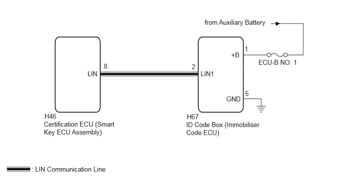
CAUTION / NOTICE / HINT
- NOTICE:
- ·
Inspect the fuses for circuits related to this system before performing the following procedure.
·If the certification ECU (smart key ECU assembly) or ID code box (immobiliser code ECU) is replaced, refer to Service Bulletin.
·When using the GTS with the ignition switch off, connect the GTS to the DLC3 and turn a courtesy light switch on and off at intervals of 1.5 seconds or less until communication between the GTS and the vehicle begins. Then select Model Code "KEY REGIST" under manual mode and enter the following menus: Body Electrical / Entry & Start (CAN). While using the GTS, periodically turn a courtesy light switch on and off at intervals of 1.5 seconds or less to maintain communication between the GTS and the vehicle.
PROCEDURE
Clear the DTCs.
- Body Electrical > Entry&Start > Clear DTCs
- 50002 440
- Result:
Proceed to NEXT
NEXT
Check for DTCs.
- Body Electrical > Entry&Start > Trouble Codes
- 50001 440
- Result:
Result Proceed to B278987 and B278588 are not output A Only B278987 is output B None of the above conditions are met C
A
Click hereGeneral>INTRODUCTION>HOW TO TROUBLESHOOT ECU CONTROLLED SYSTEMS>HOW TO PROCEED WITH TROUBLESHOOTING
B
C
Pre-procedure1
Disconnect the H67 ID code box (immobiliser code ECU) connector.
Procedure1
Measure the resistance and voltage according to the value(s) in the table below.
- Standard Resistance:
Tester Connection Condition Specified Condition Click Location & Routing(H67)Location & Routingewd_type=routing;type=c;code=H67
Click Connector(H67)Instrument Panel>Instrument Panel Wire / Speaker Wire>ID Code Boxewd_type=component;type=c;code=H67;pinno=5
H67-5 (GND) - Body ground Always Below 1 Ω
- Standard Voltage:
Tester Connection Switch Condition Specified Condition Click Location & Routing(H67)Location & Routingewd_type=routing;type=c;code=H67
Click Connector(H67)Instrument Panel>Instrument Panel Wire / Speaker Wire>ID Code Boxewd_type=component;type=c;code=H67;pinno=1
H67-1 (+B) - Body ground Ignition switch off 11 to 14 V
- Result:
Proceed to OK NG
Post-procedure1
None
OK
NG
Pre-procedure1
Disconnect the H46 certification ECU (smart key ECU assembly) connector.
Disconnect the H67 ID CODE BOX (IMMOBILISER CODE ECU) connector.
Procedure1
Measure the resistance according to the value(s) in the table below.
- Standard Resistance:
Tester Connection Condition Specified Condition Click Location & Routing(H46,H67)Location & Routingewd_type=routing;type=c,c;code=H46,H67
Click Connector(H46)Instrument Panel>Instrument Panel Wire / Speaker Wire>Certification ECUewd_type=component;type=c;code=H46;pinno=8
Click Connector(H67)Instrument Panel>Instrument Panel Wire / Speaker Wire>ID Code Boxewd_type=component;type=c;code=H67;pinno=2
H46-8 (LIN) - H67-2 (LIN1) Always Below 1 Ω
- Result:
Proceed to OK NG
Post-procedure1
None
OK
NG