BRAKE CONTROL / DYNAMIC CONTROL SYSTEMS ELECTRONICALLY CONTROLLED BRAKE SYSTEM(for HV Model TMMF Made) C127A11 Electronic Brake Booster Input Stroke Sensor "A" Circuit Short to Ground C127A15 Electronic Brake Booster Input Stroke Sensor "A" Circuit Short to Battery or Open C127A16 Electronic Brake Booster Input Stroke Sensor "A" Circuit Voltage Below Threshold C127A17 Electronic Brake Booster Input Stroke Sensor "A" Circuit Voltage Above Threshold C127A23 Electronic Brake Booster Input Stroke Sensor "A" Signal Stuck Low C127A24 Electronic Brake Booster Input Stroke Sensor "A" Signal Stuck High C127A64 Electronic Brake Booster Input Stroke Sensor "A" Signal Plausibility Failure C127A86 Electronic Brake Booster Input Stroke Sensor "A" Signal (some circuit quantity, reported via serial data) Invalid C127A96 Electronic Brake Booster Input Stroke Sensor "A" Component Internal Failure C127F1C Electronic Brake Booster Input Stroke Sensor Supply Voltage Circuit Voltage Out of Range C128A11 Electronic Brake Booster Input Stroke Sensor "B" Circuit Short to Ground C128A15 Electronic Brake Booster Input Stroke Sensor "B" Circuit Short to Battery or Open C128A64 Electronic Brake Booster Input Stroke Sensor "B" Signal Plausibility Failure C128F64 Electronic Brake Booster Input Stroke Sensor "A" / "B" Signal Plausibility Failure
DESCRIPTION
The relative displacement sensor sends the brake pedal stroke distance to the electric brake booster (brake booster with master cylinder assembly).
| DTC No. | Detection Item | DTC Detection Condition | Trouble Area | DTC Output from | Priority |
|---|---|---|---|---|---|
| C127A11 | Electronic Brake Booster Input Stroke Sensor "A" Circuit Short to Ground | Open in relative displacement sensor (brake booster with master cylinder assembly) signal circuit for 0.1 seconds or more. | ·
Wire harness or connector* ·
No. 2 engine room wire* ·
Electric brake booster (brake booster with master cylinder assembly) |
Brake Booster | A |
| C127A15 | Electronic Brake Booster Input Stroke Sensor "A" Circuit Short to Battery or Open | Short in relative displacement sensor (brake booster with master cylinder assembly) signal circuit for 0.1 seconds or more. | ·
Wire harness or connector* ·
No. 2 engine room wire* ·
Electric brake booster (brake booster with master cylinder assembly) |
Brake Booster | A |
| C127A16 | Electronic Brake Booster Input Stroke Sensor "A" Circuit Voltage Below Threshold | Relative displacement sensor (brake booster with master cylinder assembly) output value is -3.9 mm or less for 0.2 seconds or more. | ·
Wire harness or connector* ·
No. 2 engine room wire* ·
Electric brake booster (brake booster with master cylinder assembly) |
Brake Booster | A |
| C127A17 | Electronic Brake Booster Input Stroke Sensor "A" Circuit Voltage Above Threshold | Relative displacement sensor (brake booster with master cylinder assembly) output value is 3.4 mm or more for 0.2 seconds or more. | ·
Wire harness or connector* ·
No. 2 engine room wire* ·
Electric brake booster (brake booster with master cylinder assembly) |
Brake Booster | A |
| C127A23 | Electronic Brake Booster Input Stroke Sensor "A" Signal Stuck Low | Relative displacement sensor (brake booster with master cylinder assembly) output value is less than 0.6 mm for 0.3 seconds or more. | ·
Wire harness or connector* ·
No. 2 engine room wire* ·
Electric brake booster (brake booster with master cylinder assembly) |
Brake Booster | A |
| C127A24 | Electronic Brake Booster Input Stroke Sensor "A" Signal Stuck High | Any of the following conditions are met:
·
Relative displacement sensor (brake booster with master cylinder assembly) output value abnormality was detected in the previous cycle and the current cycle for 60 seconds or more. ·
Relative displacement sensor (brake booster with master cylinder assembly) output value was outside the operating range in the previous cycle and the current cycle for 300 seconds or more. ·
Relative displacement sensor (brake booster with master cylinder assembly) output value is 0.6 mm or more and within 1.5 mm for 60 seconds or more. |
·
Wire harness or connector* ·
No. 2 engine room wire* ·
Electric brake booster (brake booster with master cylinder assembly) |
Brake Booster | A |
| C127A64 | Electronic Brake Booster Input Stroke Sensor "A" Signal Plausibility Failure | Relative displacement sensor (brake booster with master cylinder assembly) output signal interrupted for 0.1 seconds or more. | ·
Wire harness or connector* ·
No. 2 engine room wire* ·
Electric brake booster (brake booster with master cylinder assembly) |
Brake Booster | A |
| C127A86 | Electronic Brake Booster Input Stroke Sensor "A" Signal (some circuit quantity, reported via serial data) Invalid | Relative displacement sensor (brake booster with master cylinder assembly) malfunction is detected for 1 second or more. | ·
Wire harness or connector* ·
No. 2 engine room wire* ·
Electric brake booster (brake booster with master cylinder assembly) |
Brake Booster | A |
| C127A96 | Electronic Brake Booster Input Stroke Sensor "A" Component Internal Failure | Relative displacement sensor (brake booster with master cylinder assembly) internal malfunction is detected for 0.1 seconds or more. | ·
Wire harness or connector* ·
No. 2 engine room wire* ·
Electric brake booster (brake booster with master cylinder assembly) |
Brake Booster | A |
| C127F1C | Electronic Brake Booster Input Stroke Sensor Supply Voltage Circuit Voltage Out of Range | Relative displacement sensor (brake booster with master cylinder assembly) power source voltage (VSK) is less than 4.8 V or more than 5.18 V for 0.08 seconds or more. | ·
Wire harness or connector* ·
No. 2 engine room wire* ·
Electric brake booster (brake booster with master cylinder assembly) |
Brake Booster | A |
| C128A11 | Electronic Brake Booster Input Stroke Sensor "B" Circuit Short to Ground | Open in relative displacement sensor (brake booster with master cylinder assembly) signal circuit for 0.2 seconds or more. | ·
Wire harness or connector* ·
No. 2 engine room wire* ·
Electric brake booster (brake booster with master cylinder assembly) |
Brake Booster | A |
| C128A15 | Electronic Brake Booster Input Stroke Sensor "B" Circuit Short to Battery or Open | Short in relative displacement sensor (brake booster with master cylinder assembly) signal circuit for 0.2 seconds or more. | ·
Wire harness or connector* ·
No. 2 engine room wire* ·
Electric brake booster (brake booster with master cylinder assembly) |
Brake Booster | A |
| C128A64 | Electronic Brake Booster Input Stroke Sensor "B" Signal Plausibility Failure | Relative displacement sensor (brake booster with master cylinder assembly) operation failure is detected for 0.2 seconds or more. | ·
Wire harness or connector* ·
No. 2 engine room wire* ·
Electric brake booster (brake booster with master cylinder assembly) |
Brake Booster | A |
| C128F64 | Electronic Brake Booster Input Stroke Sensor "A" / "B" Signal Plausibility Failure | Difference between change amounts of relative displacement sensor (brake booster with master cylinder assembly) output 1 (SKS1) and relative displacement sensor (brake booster with master cylinder assembly) output 2 (SKS2) is abnormally large for 0.2 seconds or more. | ·
Wire harness or connector* ·
No. 2 engine room wire* ·
Electric brake booster (brake booster with master cylinder assembly) |
Brake Booster | A |
*: for RHD
WIRING DIAGRAM
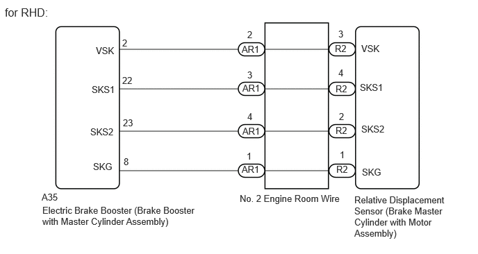
CAUTION / NOTICE / HINT
- NOTICE:
-
After replacing the electric brake booster (brake booster with master cylinder assembly), perform "Calibration" after performing "Reset Memory".
PROCEDURE
Check the vehicle specification.
- Result:
Result Proceed to for LHD A for RHD B
A
B
- Result:
Proceed to NEXT
NEXT
Procedure1
Make sure that there is no looseness at the locking part and the connecting part of the connector.
- OK:
The connector is securely connected.
Pre-procedure1
Disconnect the A35 electric brake booster (brake booster with master cylinder assembly) connector.
Disconnect the AR1 No. 2 engine room wire connector.
Procedure2
Measure the resistance according to the value(s) in the table below.
- Standard Resistance:
Tester Connection Condition Specified Condition Click Location & Routing(A35,AR1)Location & Routingewd_type=routing;type=c,w;code=A35,AR1
Click Connector(A35)Engine Compartment>Engine Room Main Wire>Brake Booster Control ECU (Brake Booster with Master Cylinder Assembly)ewd_type=component;type=c;code=A35;pinno=2,22,23,8
Click Connector(AR1)Engine Compartment>Engine Room Main Wire>Engine Room Main Wire and No. 2 Engine Room Wireewd_type=component;type=w;code=AR1;pinno=2,3,4,1
A35-2 (VSK) - AR1-2 Always Below 1 Ω A35-2 (VSK) or AR1-2 - Body ground Always 10 kΩ or higher A35-22 (SKS1) - AR1-3 Always Below 1 Ω A35-22 (SKS1) or AR1-3 - Body ground Always 10 kΩ or higher A35-23 (SKS) - AR1-4 Always Below 1 Ω A35-23 (SKS) or AR1-4 - Body ground Always 10 kΩ or higher A35-8 (SKG) - AR1-1 Always Below 1 Ω A35-8 (SKG) or AR1-1 - Body ground Always 10 kΩ or higher
- Result:
Proceed to OK NG
Post-procedure1
None
OK
NG