RM3700E
_58
Vehicle Interior
_093747
DOOR LOCK
_0445088
DOOR CONTROL SWITCH
G
DOOR LOCK DOOR CONTROL SWITCH INSPECTION
PROCEDURE

 84040
1.INSPECT MULTIPLEX NETWORK MASTER SWITCH ASSEMBLY
Pre-procedure
a.
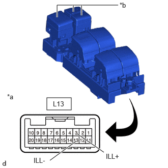
0.958,2 1.458,2.25
0.5,0.25
1.583,2.74 2.125,3.115
true
1.021,3.281 1.563,2.885
true
2.417,0.104 1.167,0.104
1.167,0.104 1.167,0.354
true
1.667,0.104 1.667,0.313
true
1.5,0.104 1.5,0.24
true
0.146,1.896 0.458,2.094
0.313,0.198
10
false
*a
2.167,3.115 2.781,3.313
0.615,0.198
10
false
ILL+
0.688,3.198 1.302,3.396
0.615,0.198
10
false
ILL-
2.448,0.021 2.76,0.219
0.313,0.198
10
false
*b
1.083,2.042 1.615,2.292
0.531,0.25
10
false
L13
| *a | Component without harness connected
(Multiplex Network Master Switch Assembly) |
| *b | LED Illumination |
Apply auxiliary battery voltage to the multiplex network master switch assembly and check that the LED illuminates.
Procedure
b.
Check that the LED illuminates.
- OK:
Tester Connection Specified Condition Click Location & Routing(L13)Location & Routingewd_type=routing;type=c;code=L13
Click Connector(L13)Body>Front Door Wire LH / Television Camera Wire>Multiplex Network Master Switch Assemblyewd_type=component;type=c;code=L13;pinno=3,13
Auxiliary battery positive (+) - L13-3 (ILL+) LED illuminates Auxiliary battery positive (-) - L13-13 (ILL-) LED illuminates
c.
If the result is not as specified, replace the multiplex network master switch assembly.
Post-procedure
d.
None