WHEN REMOVING,INSTALLING,REPAIRING OR REPLACING PARTS (for Sedan) > WHEEL ALIGNMENT STANDARD |
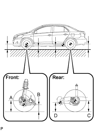
| MEASURE VEHICLE HEIGHT |
|
| Destination | A-B | C-D |
| Except for Rough Road Package | 87 mm (3.43 in.) | 16 mm (0.63 in.) |
| Rough Road Package | 67 mm (2.64 in.) | -2 mm (-0.08 in.) |
| INSPECT CAMBER, CASTER AND STEERING AXIS INCLINATION |
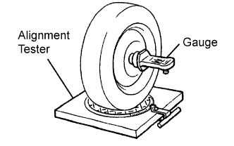 |
Put the front wheel on the center of the alignment tester.
Remove the wheel cap.
Set the camber-caster-steering axis inclination gauge at the center of the axle hub or drive shaft.
Inspect the camber, caster and steering axis inclination.
| Destination | Camber | Caster | Steering Axis Inclination (Reference) |
| Except for Rough Road Package | -0°10' +/- 45' (-0.17°+/- 0.75°) | 4°39' +/- 45' (4.65°+/- 0.75°) | 11°16' (11.27°) |
| Rough Road Package | 0°06' +/- 45' (0.10°+/- 0.75°) | 4°23' +/- 45' (4.38°+/- 0.75°) | 10°47' (10.78°) |
Remove the camber-caster-steering axis inclination gauge and attachment.
Install the wheel cap.
If the caster and steering axis inclination are not within the specified values after the camber has been correctly adjusted, recheck the suspension parts for damage and wear.
| INSPECT TOE-IN |
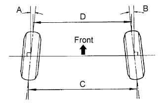 |
| A+B | C-D |
| 0°09' +/- 0°13' (0.15° +/- 0.22°) | 1.5 +/- 2.0 mm (0.06 +/- 0.08 in.) |
| INSPECT WHEEL TURNING ANGLE |
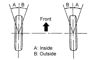 |
Fully turn the steering wheel left and right, and measure the wheel turning angle.
| Destination | Inside Wheel | Outside Wheel (Reference) |
| Except for Rough Road Package | 40°57' +/- 2° (40.95° +/- 2°) | 35°17' (35.29°) |
| Rough Road Package | 41°22' +/- 2° (41.37° +/- 2°) | 35°45' (35.75°) |