Air Conditioning Control Assembly
The rotary switch type air conditioning control assembly is used.
The '07 models use 2 cables on pulleys to operate the air conditioning control assembly and damper.
5 air outlet modes are provided on the control panel on the models with air conditioning. To realize finer mode settings, a positive feel is provided between the positions of these modes, thus realizing the high comfort level.
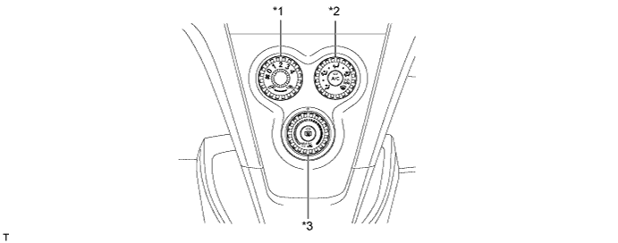
Text in Illustration *1 Heater Control Sub-assembly *2 Heater Control Base Sub-assembly *3 No. 2 Heater Control Knob - - The '07 models use 2 cables on pulleys that are always operated in the pulling direction to operate the air conditioning control assembly and damper.
This cable is circular, and is placed around the cable pulleys that are provided at the air conditioning control assembly and the damper.
The operation of the air conditioning control assembly is transmitted to the damper via the control cable, which always moves in the pulling direction. Due to the consistent action point of the pulleys, the fluctuation of the operating effort has been minimized through the use of the pulleys. These measures have ensured the ease of use and reduced the operating effort.
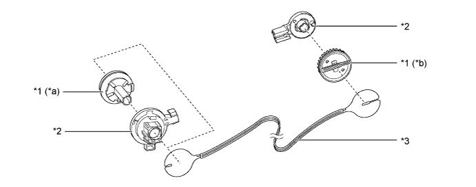
Text in Illustration *1 Pulley *2 Base of Pulley *3 Control Cable - - *a Air Conditioning Control Assembly Side *b Damper Side
Air Conditioning Unit
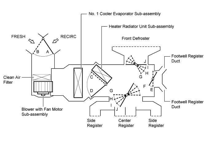
A semi-center location air conditioning unit in which the No. 1 cooler evaporator sub-assembly and heater radiator unit sub-assembly are placed in the vehicle's longitudinal direction is used.
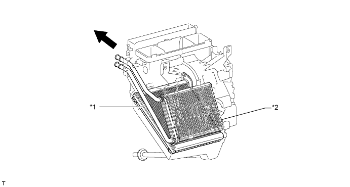
Text in Illustration *1 No. 1 Cooler Evaporator Sub-assembly *2 Heater Radiator Unit Sub-assembly 
Front - -
No. 1 Cooler Evaporator Sub-assembly
A Revolutionary super-Slim structure (RS) evaporator is used. Placing the tanks at the top and the bottom of the evaporator and adopting a micropore tube construction have realized the following effects:
- The heat exchanging efficiency is ensured.
- The temperature distribution is made uniform.
- The evaporator is made thinner: 58 mm (2.3 in.) to 38 mm (1.5 in.)
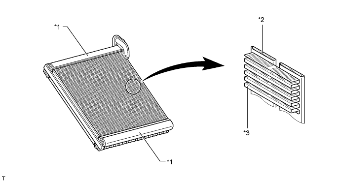
Text in Illustration *1 Tank *2 Micropore Tube *3 Cooling Fin - - - The heat exchanging efficiency is ensured.
Heater Radiator Unit Sub-assembly
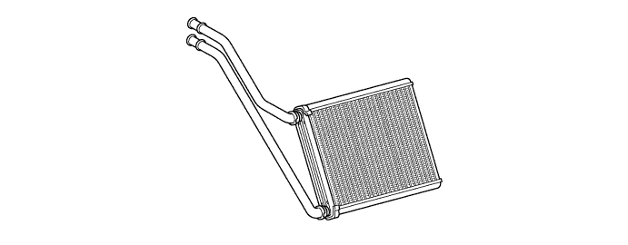
The heater radiator unit sub-assembly has been made more compact and higher performance by making the core section finer and improving the shapes of the tank section and flow section. Also, the environment is considered. By using aluminum as the material, the amount of the environmental burden disposal (lead) is reduced.
Cooler Condenser Assembly
A sub-cool condenser is used. This is a multi-flow condenser consisting of 3 portions: a condensing portion, super-cooling portion, and gas-liquid separator (modulator) all integrated together. This cooler condenser assembly uses a sub-cool cycle for its cooling cycle system to ensure heat-exchanging efficiency.
In the sub-cool cycle, after the refrigerant passes through the condensing portion of the condenser, both the liquid refrigerant and the gaseous refrigerant that could not be liquefied are cooled again in the super-cooling portion. Thus, the refrigerant is sent to the evaporator in an almost completely liquefied state.
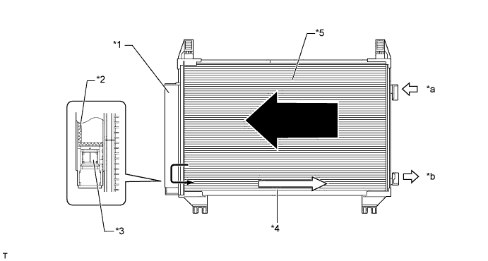
Text in Illustration *1 Modulator *2 Desiccant *3 Filter *4 Super-cooling Portion *5 Condensing Portion - - *a Gaseous Refrigerant *b Liquid Refrigerant - HINT:
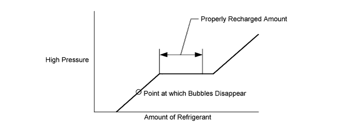
- The point at which the air bubbles disappear in the refrigerant of the sub-cool cycle is lower than the proper amount of refrigerant with which the system must be filled. Therefore, if the system is recharged with refrigerant based on the point at which the air bubbles disappear, the amount of refrigerant would be insufficient. As a result, the cooling performance of the system will be affected. If the system is overcharged with refrigerant, this will also lead to a reduced performance. For the proper method of verifying the amount of the refrigerant and to recharge the system with refrigerant, refer to the Repair Manual.
Compressor with Pulley Assembly
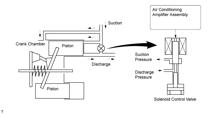
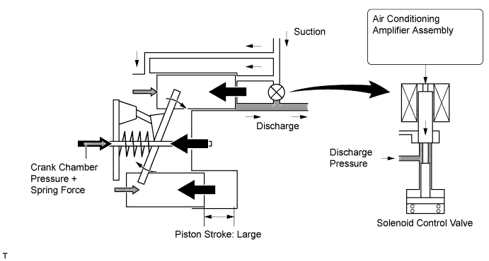
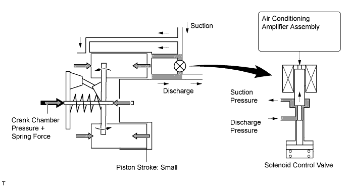
A compressor with pulley assembly is a continuously variable capacity type in which its capacity varies in accordance with the cooling load of the air conditioning.
This compressor consists of the shaft, lug plate, piston, shoe, crank chamber, cylinder and solenoid control valve.
The solenoid control valve that adjusts the suction pressure so that the suction pressure can be controlled as desired is provided.
The Damper Limiter (DL) pulley is used.
A rotary valve type is used to suction refrigerant gas into the cylinder.
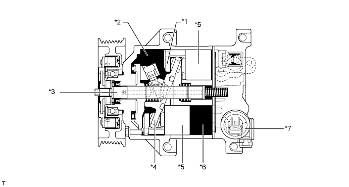
Text in Illustration *1 Shoe *2 Crank Chamber *3 Shaft *4 Lug Plate *5 Piston *6 Cylinder *7 Solenoid Control Valve - - The rotary valve type achieves the following excellent effects in comparison to the conventional lead valve type.
- Decreases suction loss of refrigerant gas
- Recovers reexpanded gas
- Decreases discharge loss
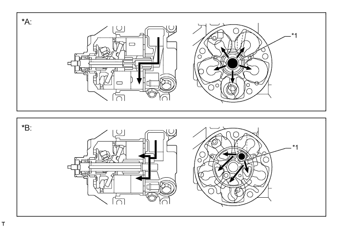
Text in Illustration *A Rotary Valve Type *B Lead Valve Type *1 Suction Port - - Suction Gas Flow - - - Decreases suction loss of refrigerant gas
This pulley contains a damper to absorb the torque fluctuations of the engine and a limiter mechanism to protect the drive belt in case the compressor locks. In the event that the compressor locks, the limiter mechanism causes the spoke portion of the pulley to break, thus separating the pulley from the compressor. To reduce weight, the pulley portion is made of plastic.
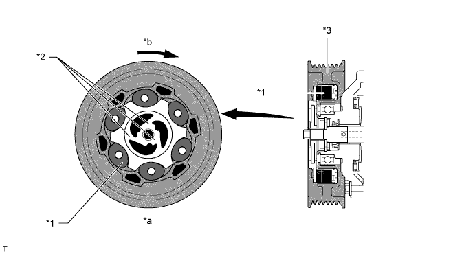
Text in Illustration *1 Damper *2 Spoke Portions *3 Pulley Portion (Plastic) - - *a Limiter Mechanism *b Rotate Direction
Clean Air Filter
A clean air filter (high efficiency type) is used to remove dust, pollen and other micron particles from air entering from outside the vehicle to provide a comfortable cabin of clean air. The clean air filter is installed in the upper section of the blower fan for easy replacement of the clean air filter without the need for tools by removing the one-touch clip in the glove box, making this easy to service.