Cylinder Head Sub-assembly
The fuel injector assemblies are installed in the cylinder head sub-assembly to reduce the distance from fuel injector assembly to intake valve, thus it prevents the fuel from adhering to the intake port walls, and reduce exhaust emissions.
The routing of the water jacket in the cylinder head sub-assembly is optimized to achieve high cooling performance.
Through the use of the taper squish combustion chamber, the engine's knocking resistance and fuel efficiency have been improved.
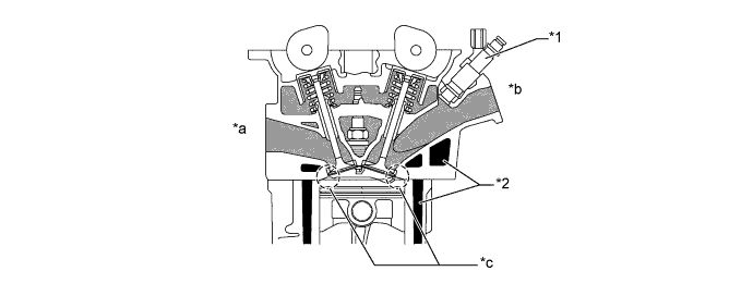
Text in Illustration *1 Fuel Injector Assembly *2 Water Jacket *a Exhaust Side *b Intake Side *c Taper Squish - -
Cylinder Block Sub-assembly
Lightweight aluminum alloy is used for the cylinder block sub-assembly.
The liners are the spiny-type, which have been manufactured so that their casting exterior forms a large irregular surface in order to enhance the adhesion between the liners and the aluminum cylinder block sub-assembly. The enhanced adhesion helps improve heat dissipation, resulting in a lower overall temperature and heat deformation of the cylinder bores.
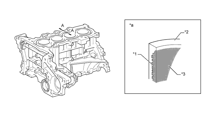
Text in Illustration *1 Irregularly Shaped Outer Casting Surface of Liner *2 Cylinder Block Sub-assembly *3 Spiny Type Liner - - *a A-A Cross Section - - Through the use of the offset crankshaft, the bore center is shifted 12 mm (0.472 in.) towards the intake in relation to the centerline crankshaft. Thus, the side force (thrust) applied to the cylinder wall is reduced when the maximum pressure is applied this contributes to fuel economy.
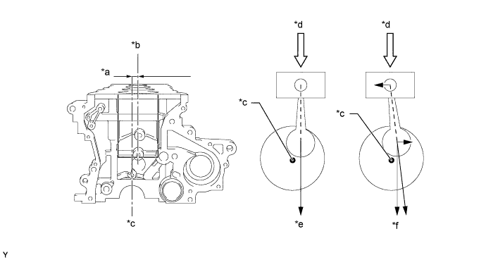
Text in Illustration *a 12mm (0.472 in.) *b Bore Centerline *c Crankshaft Centerline *d Maximum Pressure *e Offset Crankshaft *f Non-offset Crankshaft
Oil Pan Sub-assembly
The oil pan sub-assembly is made of aluminum die-cast.
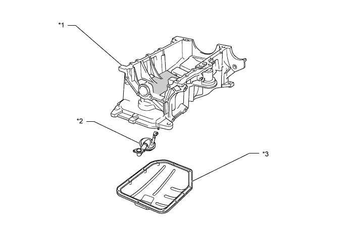
Text in Illustration *1 Oil Pan Sub-assembly *2 Oil Strainer Sub-assembly *3 No. 2 Oil Pan Sub-assembly - -
Piston
The pistons are made of aluminum alloy to allow them to be compact and lightweight.
The piston head portion uses a taper squish shape to achieve fuel combustion efficiency.
Semi-floating type piston pins are used.
By increasing the machining precision of the cylinder bore diameter, only one size of piston is available.
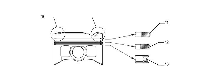
Text in Illustration *1 No. 1 Compression Ring *2 No. 2 Compression Ring *3 Oil Ring - - *a Taper Squish Shape - -
Connecting Rod Sub-assembly
The connecting rod sub-assemblies and caps are made of high strength steel for weight reduction.
Plastic region tightening bolts are used to achieve a light weight.
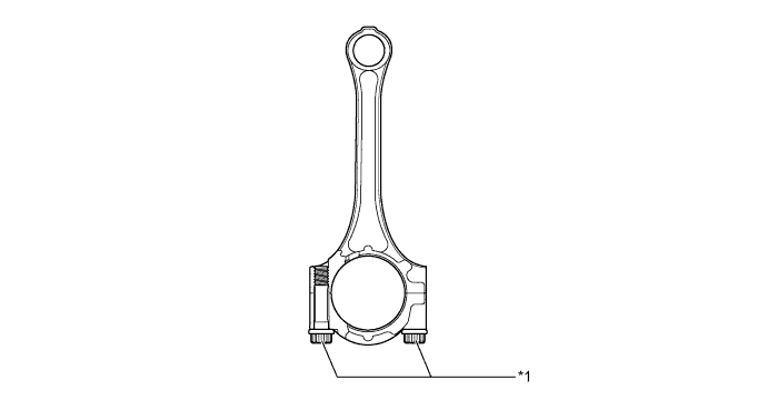
Text in Illustration *1 Plastic Region Tightening Bolt - -
Crankshaft
The diameter and width of the pins and journals have been reduced, and the pins for the No. 1 and No. 4 cylinders have been made highly rigid to realize a lightweight and low-friction performance.
The crankshaft has 5 journals and 4 balance weights.
A crankshaft position sensor rotor is pressed into the crankshaft to realize an integrated configuration.
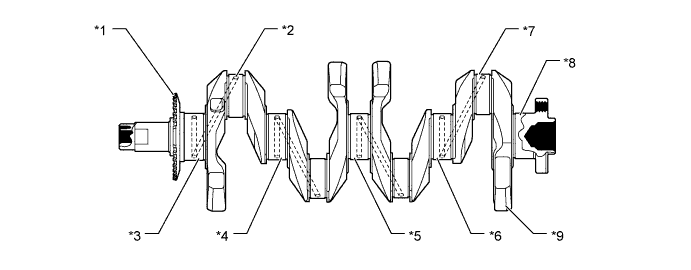
Text in Illustration *1 Crankshaft Position Sensor Rotor *2 Oil Hole *3 No. 1 Journal *4 No. 2 Journal *5 No. 3 Journal *6 No. 4 Journal *7 Crank Pin *8 No. 5 Journal *9 Balance Weight - -
Valve Mechanism
The shimless type valve lifter is used to increase the amount of the valve lift.
The intake and exhaust camshafts are driven by a chain sub-assembly.
The VVT-i system is used to realize fuel economy, engine performance and reduce exhaust emissions. For details of VVT-i control.
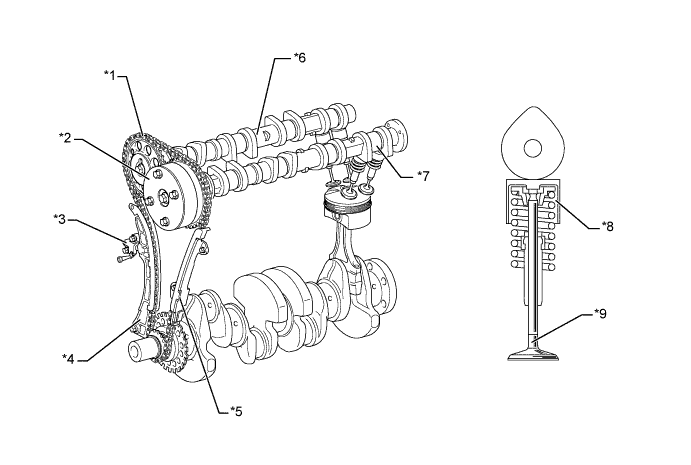
Text in Illustration *1 Chain Sub-assembly *2 Camshaft Timing Gear Assembly *3 No. 1 Chain Tensioner Assembly *4 Chain Tensioner Slipper *5 No. 1 Chain Vibration Damper *6 No. 2 Camshaft *7 Camshaft *8 Valve Lifter *9 Valve - -
Camshaft
Oil passages are provided in the camshaft in order to supply engine oil pressure to the VVT-i system.
A VVT-i controller (camshaft timing gear assembly) is provided on the front of the camshaft to vary the timing of the intake valves.
A timing rotor is provided behind the camshaft to trigger the cam position sensor.
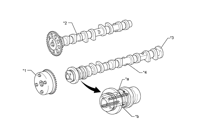
Text in Illustration *1 VVT-i Controller (Camshaft Timing Gear Assembly) *2 No. 2 Camshaft *3 Timing Rotor *4 Camshaft *a Oil Passage (Advance) *b Oil Passage (Retard)
VVT-I Controller (Camshaft Timing Gear Assembly)
The VVT-i controller (camshaft timing gear assembly) consists of the housing driven from the chain sub-assembly and the vane coupled with the camshaft.
The oil pressure sent from the advance or retard side path at the camshaft causes rotation in the VVT-i controller (camshaft timing gear assembly) vane circumferential direction to vary the intake valve timing continuously.
When the engine is stopped, the camshaft will be in the most retarded state to ensure startability.
When hydraulic pressure is not applied to the VVT-i controller (camshaft timing gear assembly) immediately after the engine has been started, the lock pin locks the movement of the VVT-i controller (camshaft timing gear assembly) to prevent a knocking noise.
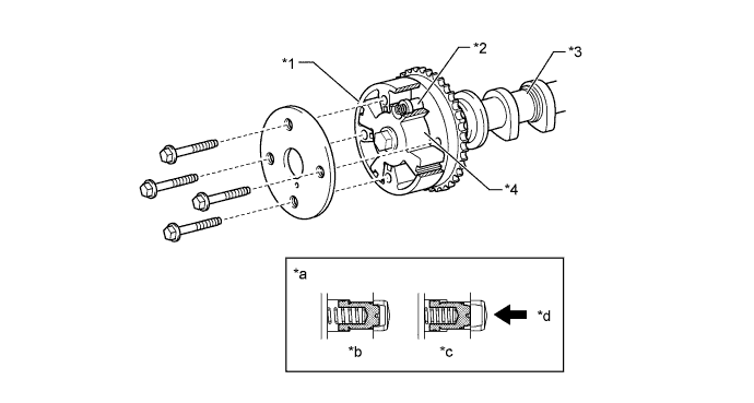
Text in Illustration *1 Housing *2 Lock pin *3 Camshaft *4 Vane *a Lock Pin Operation *b Engine Stopped *c Engine Operating *d Oil Pressure
Chain Sub-assembly and No. 1 Chain Tensioner Assembly
A roller type chain sub-assembly with an 8.0 mm (0.315 in.) pitch is used to make the engine compact and reduce noise.
The chain sub-assembly is lubricated by an oil jet.
The No. 1 chain tensioner assembly uses a spring and oil pressure to maintain proper chain tensioner at all times. The No. 1 chain tensioner assembly suppresses noise generated by the chain sub-assembly.
A ratchet type non-return mechanism is used in the No. 1 chain tensioner assembly.
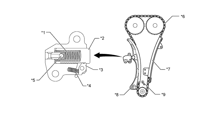
Text in Illustration *1 Spring *2 Plunger *3 Cam *4 Cam Spring *5 Check Ball *6 Chain Sub-assembly *7 No. 1 Chain Vibration Damper *8 Chain Tensioner Slipper *9 Oil Jet - -
Timing Chain Cover (Oil Pump Assembly)
A single-piece, aluminum die-cast timing chain cover (oil pump assembly) that entirely seals the front portion of the cylinder block sub-assembly and cylinder head sub-assembly is used.
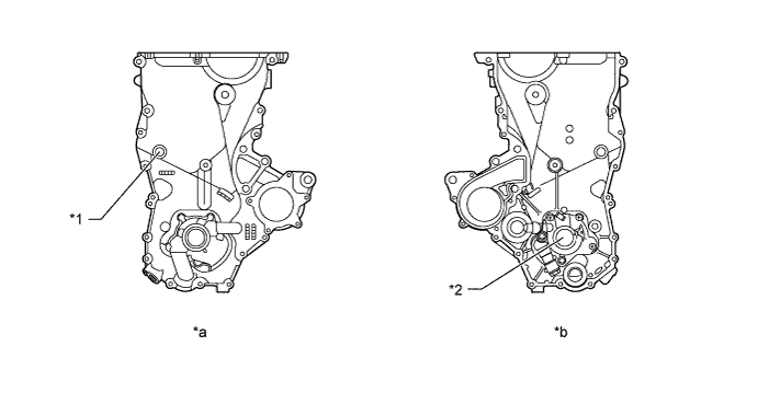
Text in Illustration *1 Service Hole for Chain Tensioner *2 Oil Pump *a Front View *b Back View