BRAKE CONTROL SYSTEM (for Sedan) > DETAILS


FUNCTION OF MAIN COMPONENTS
  1. ABS with EBD

    Component
    Function
    Brake Actuator
    Skid Control ECU
    Based on signals from each sensor, it judges the vehicle driving condition and sends brake control signal to the brake actuator.
    Solenoid Valve (8)
    Changes the fluid path based on the signals from the skid control ECU during the operation of the ABS with EBD, in order to control the fluid pressure that is applied to the wheel cylinders.
    Pump Motor
    Drives the pumps inside the brake actuator.
    Solenoid Relay
    Supplies or cuts off power to the solenoid valves in the brake actuator.
    Motor Relay
    Supplies or cuts off power to the motor in the brake actuator.
    Speed Sensor (4)
    Detect the wheel speed of each of the 4 wheels.
    Stop Light Switch
    Detects the brake pedal depressing signal.
    Parking Brake Switch
    Detects when the parking brake lever is pulled up.
    Brake Fluid Level Warning Switch
    Detects the brake fluid level.
    Combination Meter Assembly
    Brake Warning Light
    1. Lights up to alert the driver when a malfunction occurs in the ABS, EBD or skid control ECU.
    2. Lights up to inform the driver when the parking brake lever is pulled up.
    3. Lights up to alert the driver when the brake fluid level is low.


SYSTEM CONTROL
  1. Control List

    1. The brake control system (ABS with EBD) has the following controls:

      Control
      Outline
      Anti-lock Brake System (ABS)
      The ABS helps prevent the wheels from locking when the brakes are applied firmly or when braking on a slippery surface.
      Electronic Brake Force Distribution (EBD)
      The EBD control utilizes ABS, realizing proper brake force distribution between the front and rear wheels in accordance with the driving conditions. In addition, during braking while cornering, it also controls the brake forces of the right and left wheels, helping maintain vehicle behavior.

  2. Anti-lock Brake System (ABS)

    1. The ABS prevents the wheels from locking during sudden braking or braking on a slippery surface. This provides the proper braking force when the vehicle slips, thus ensuring vehicle stability and excellent braking performance.


  3. Electronic Brake Force Distribution (EBD)

    1. The distribution of the brake force, which was performed mechanically in the past, is now performed under electrical control of the skid control ECU, which controls the braking force in accordance with the vehicle's driving conditions.


    2. If the brakes are applied while the vehicle is moving straight forward, the transfer of the load reduces the weight that is applied to the rear wheels. The skid control ECU determines this condition by way of the signals from the speed sensor, and the brake actuator regulates the distribution of the brake force of the rear wheels to optimally control. For example, the amount of the brake force that is applied to the rear wheels during braking varies depending on whether the vehicle is carrying load or not. The amount of the brake force that is applied to the rear wheels also varies in accordance with the extent of the deceleration. Thus, the distribution of the brake force to the rear is optimally controlled in order to effectively utilize the braking force of the rear wheels under these conditions.
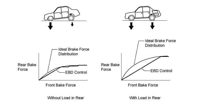

      X106019E01

    3. When the brakes are applied while the vehicle is cornering, the load that is applied to the inner wheel decreases as the load to the outer wheel increases. The skid control ECU determines this condition by way of the signals from the speed sensor, and the brake actuator regulates the brake force in order to optimally control the distribution of the brake force to the inner wheel and outer wheel.
CONSTRUCTION


  1. Brake Actuator Assembly

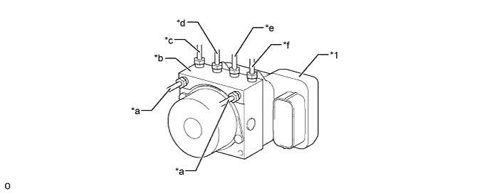
    1. The brake actuator consists of the actuator portion and skid control ECU.


    2. The actuator portion regulates the hydraulic brake pressure to each wheel cylinder.


      X106030E01


      Text in Illustration 
      *1
      Skid Control ECU
      -
      -
      *a
      From Master Cylinder
      *b
      Actuator Portion
      *c
      To Front Wheel Cylinder RH
      *d
      To Rear Wheel Cylinder LH
      *e
      To Rear Wheel Cylinder RH
      *f
      To Front Wheel Cylinder LH


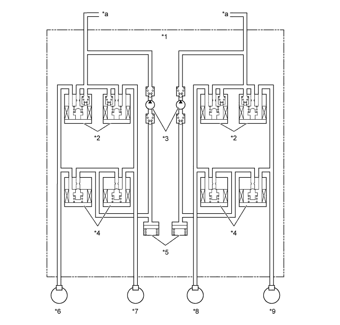
    3. The brake actuator is constructed with the following hydraulic circuit:


      X106083E01


      Text in Illustration 
      *1
      Brake Actuator Assembly
      *2
      Pressure Holding Solenoid Valve
      *3
      Pump Motor
      *4
      Pressure Reduction Solenoid Valve
      *5
      Reservoir
      *6
      Front Left Wheel Cylinder
      *7
      Rear Right Wheel Cylinder
      *8
      Rear Left Wheel Cylinder
      *9
      Front Right Wheel Cylinder
      -
      -
      *a
      From Master Cylinder
      -
      -


  2. Speed Sensor

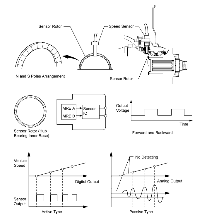
    1. An active type speed sensor is used. A Hall IC is used in the sensing portion of this sensor.


    2. The sensor rotor, which consists of N and S poles that are arranged in a circle, is integrated with the hub bearing inner race.


      X106085E02


OPERATION
  1. ABS with EBD

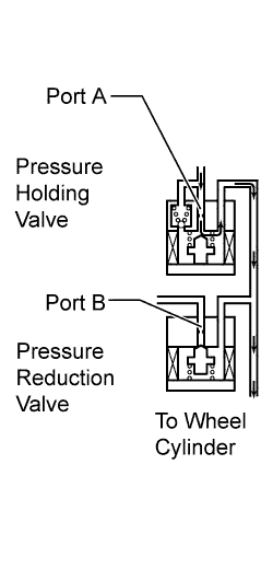
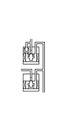
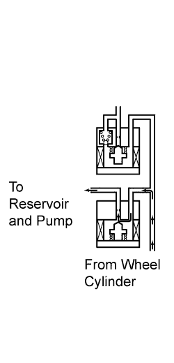
    1. Based on the signals received from the 4 speed sensors, the skid control ECU calculates each wheel speed and deceleration, and checks wheel slipping conditions. According to the slipping condition, the skid control ECU controls the pressure holding valve and pressure reduction valve in order to adjust the fluid pressure of the each wheel cylinder in the following 3 modes: pressure reduction, pressure holding, and pressure increase modes.

      Not Activated
      Normal Braking
      -
      -
      Activated
      Increase Mode
      Holding Mode
      Reduction Mode
      Hydraulic Circuit
      X106111E01
      X106112
      X106113E01
      Pressure Holding Valve (Port A)
      OFF (Open)
      ON (Closed)
      ON (Closed)
      Pressure Reduction Valve (Port B)
      OFF (Closed)
      OFF (Closed)
      ON (Open)
      Brake Wheel Cylinder Pressure
      Increased
      Held
      Reduced


FAIL-SAFE
  1. In the event of a malfunction in the ABS, the skid control ECU prohibits the ABS operation.

  2. In the event of a malfunction in EBD control, the skid control ECU prohibits EBD control. Thus, the brake will be operated in the same condition as the system without the ABS with EBD.


DIAGNOSIS
  1. If the skid control ECU detects a malfunction in the ABS with EBD, the brake warning light that corresponds to the function in which the malfunction has been detected indicate or light up to alert the driver of the malfunction.

  2. At the same time, Diagnostic Trouble Code (DTC) is stored in memory of the skid control ECU.

  3. This system has a sensor signal check (test mode) function.

  4. For details of the DTC that are stored in skid control ECU memory and the DTC that are output through the sensor signal check functions, see the Repair Manual.