Home › Drivetrain ยท DRIVE SHAFT / PROPELLER SHAFT › FRONT DRIVE SHAFT ASSEMBLY (for TMMF Made Hatchback)

FRONT DRIVE SHAFT ASSEMBLY (for TMMF Made Hatchback) > INSTALLATION


1. INSTALL FRONT DRIVE SHAFT HOLE SNAP RING
  1. Install a new front drive shaft hole snap ring.

    HINT:
    Use the same procedure for the RH side as for the LH side.


2. INSTALL FRONT DRIVE SHAFT ASSEMBLY LH


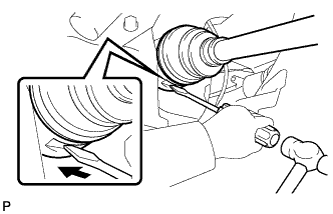
C116899
  1. Coat the spline of the inboard joint with gear oil.

  1. Align the inboard joint splines and install the drive shaft with a screwdriver and hammer.

    NOTICE:
    1. Face the cut area of the front drive shaft hole snap ring downward.
    2. Do not damage the oil seal.
    3. Do not damage the inboard joint boot.

    HINT:
    Confirm whether the drive shaft is securely driven in by checking the reaction force and sound.


3. INSTALL FRONT DRIVE SHAFT ASSEMBLY RH

HINT:
Use the same procedure for the RH side as for the LH side.


4. INSTALL FRONT AXLE ASSEMBLY LH
  1. Push the front axle out of the vehicle to align the spline of the drive shaft with the front axle and insert the front axle.

    NOTICE:
    1. Do not push the front axle further out of the vehicle than is necessary.
    2. Do not damage the outboard joint boot.
    3. Check for any foreign matter on the speed sensor rotor and insertion part.
    4. Do not damage the speed sensor rotor.


5. INSTALL FRONT AXLE ASSEMBLY RH

HINT:
Use the same procedure for the RH side as for the LH side.


6. INSTALL FRONT LOWER SUSPENSION ARM SUB-ASSEMBLY LH
  1. Install the lower arm onto the steering knuckle with a new castle nut.

    Torque:
    98 N*m{ 999 kgf*cm , 72 ft.*lbf }

    NOTICE:
    If the holes for the clip are not aligned, tighten the nut by a further turn of up to 60°.

  1. Install a new clip.


7. INSTALL FRONT LOWER SUSPENSION ARM SUB-ASSEMBLY RH

HINT:
Use the same procedure for the RH side as for the LH side.


8. INSTALL TIE ROD END SUB-ASSEMBLY LH
  1. Install the tie rod end sub-assembly onto the steering knuckle with a new castle nut.

    Torque:
    49 N*m{ 500 kgf*cm , 36 ft.*lbf }

    NOTICE:
    If the holes for the clip are not aligned, tighten the nut by a further turn of up to 60°.

  1. Install a new cotter pin.


9. INSTALL TIE ROD END SUB-ASSEMBLY RH

HINT:
Use the same procedure for the RH side as for the LH side.


10. INSTALL FRONT STABILIZER LINK ASSEMBLY LH
  1. Install the front stabilizer link assembly LH with the nut.

    Torque:
    74 N*m{ 755 kgf*cm , 55 ft.*lbf }

    HINT:
    Using a socket hexagon wrench 6 to hold the stud.


11. INSTALL FRONT STABILIZER LINK ASSEMBLY RH

HINT:
Use the same procedure for the RH side as for the LH side.


12. INSTALL FRONT SPEED SENSOR LH
  1. Install the speed sensor onto the steering knuckle with the bolt.

    Torque:
    8.5 N*m{ 87 kgf*cm , 75 in.*lbf }

    NOTICE:
    1. Check that the speed sensor tip and installation portion are free of foreign matter.
    2. Install the speed sensor without turning it from its original installation angle.

  1. Install the front flexible hose and speed sensor to the front shock absorber with the bolt.

    Torque:
    29 N*m{ 300 kgf*cm , 22 ft.*lbf }

    NOTICE:
    Install the flexible hose and speed sensor without twisting them.


13. INSTALL FRONT SPEED SENSOR RH

HINT:
Use the same procedure for the RH side as for the LH side.


14. INSTALL FRONT AXLE SHAFT NUT LH
  1. Clean the threaded parts on the front drive shaft and axle shaft nut using a non-residue solvent.

    NOTICE:
    1. Be sure to perform this work for a new front drive shaft.
    2. Keep the threaded parts free of oil and foreign objects.

  1. Using a deep socket wrench 30 mm, install a new front axle shaft nut.
    Torque:
    216 N*m{ 2203 kgf*cm , 159 ft.*lbf }


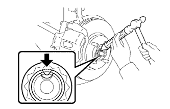
    C235879
  1. Using a chisel and hammer, stake the axle shaft nut.


15. INSTALL FRONT AXLE SHAFT NUT RH

HINT:
Use the same procedure for the RH side as for the LH side.


16. ADD MANUAL TRANSAXLE OIL


    D025304E50
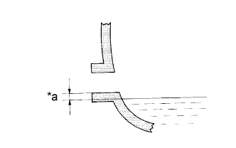
  1. Add manual transmission oil until the oil level is within 5 mm (0.197 in.) from the bottom of the manual transmission filler plug opening.
    Text in Illustration 
    *a
    0 to 5 mm (0 to 0.197 in.)

    Manual Transaxle Oil:
    "Toyota Genuine Manual Transmission Gear Oil LV", "API GL-4 and SAE 75W" or "API GL-4 and SAE 75W-90"
    Standard Capacity:
    1.9 Liters (2.0 US qts, 1.7 Imp. qts)

    NOTICE:
    1. Problems may occur if the oil level is too high or low.
    2. After replacing the oil, drive the vehicle and check the oil level again.

  1. Check for oil leakage when the oil level is low.

  1. Install the transmission filler plug and a new gasket.

    Torque:
    39 N*m{ 400 kgf*cm , 29 ft.*lbf }


17. ADD AUTOMATIC TRANSAXLE FLUID

Automatic Transaxle Fluid:
Classification
Capacity
(Reference)
Toyota Genuine ATF WS
Dry fill
6.4 liters (6.8 US qts, 5.6 Imp. qts)
Drain and refill
2.5 liters (2.6 US qts, 2.2 Imp. qts)


18. INSPECT FOR OIL LEAK


19. INSTALL ENGINE UNDER COVER RH


20. INSTALL ENGINE UNDER COVER LH


21. INSTALL FRONT WHEEL

Torque:
103 N*m{ 1050 kgf*cm , 76 ft.*lbf }


22. INSPECT AND ADJUST FRONT WHEEL ALIGNMENT
(Click here)