STEERING COLUMN ASSEMBLY (for Hatchback) > REASSEMBLY |
| 1. INSTALL POWER STEERING MOTOR ASSEMBLY |
|
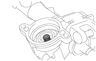
Apply grease to the serrated part of the electric power steering column sub-assembly.
Temporarily install the power steering motor assembly to the electric power steering column sub-assembly with the 2 bolts.
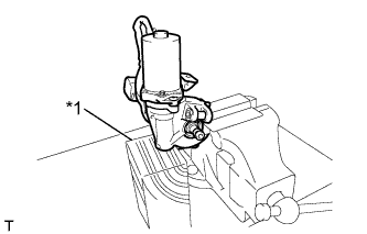 |
Secure the steering column assembly in a vise using aluminum plates.
| *1 | Wooden Block |
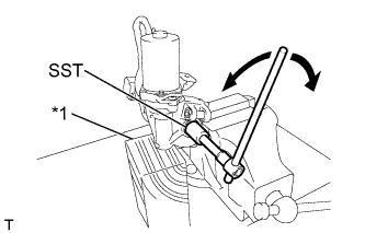 |
Using SST, turn the steering main shaft once 180 degrees to the left and then 180 degrees to the right at a speed of 60 rpm, and repeat 2 to 3 times to adjust the axis centering of the power steering motor assembly.
| *1 | Wooden Block |
Tighten the 2 bolts.
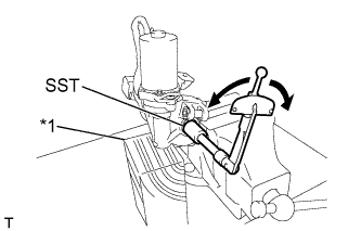 |
Using SST, measure the turning torque of the steering main shaft.
| *1 | Wooden Block |
Install a new clamp and tape to the wire harness as shown in the illustration.
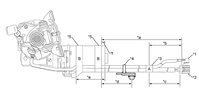
| *1 | Torque Sensor Wire Harness | *2 | Power Steering Motor Wire Harness |
| *3 | Tape A | *4 | Clamp |
| *5 | Tape B | - | - |
| *a | 383 to 403 mm (1.256 to 1.322 ft.) | *b | 100 mm (3.937 in.) |
| *c | 80 to 100 mm (3.150 to 3.937 in.) | *d | 155 to 175 mm (6.102 to 6.890 in.) |
| *e | 74 to 94 mm (2.913 to 3.701 in.) | *f | 10 mm (0.394 in.) |
| 2. INSTALL IGNITION OR STARTER SWITCH ASSEMBLY |
Engage the 2 claws to install the ignition or starter switch assembly onto the upper steering column bracket assembly.
| 3. INSTALL KEY INTER LOCK SOLENOID (for Automatic Transaxle) |
Install the key inter lock solenoid onto the upper steering column bracket assembly with the screw.
| 4. INSTALL UNLOCK WARNING SWITCH ASSEMBLY |
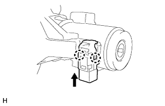 |
Engage the 2 claws to install the unlock warning switch assembly onto the upper steering column bracket assembly.
| 5. INSTALL IGNITION SWITCH LOCK CYLINDER ASSEMBLY |
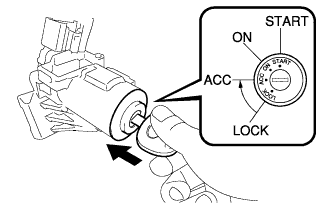 |
Turn the ignition switch to ACC.
Install the ignition switch lock cylinder assembly into the upper steering column bracket assembly.
Make sure that the ignition switch lock cylinder assembly is securely fixed onto the ignition switch lock cylinder assembly.
| 6. INSTALL UPPER STEERING COLUMN BRACKET ASSEMBLY |
Set the steering column assembly in a vise between aluminum plates.
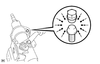 |
Install the steering column upper with switch bracket assembly with a new steering lock set bolt, and then tighten the bolt until its head comes off.
| 7. INSTALL STEERING FLEXIBLE COUPLING BOLT CLAMP |
Install the steering flexible coupling bolt clamp to the steering column assembly.
| 8. INSTALL NO. 2 STEERING INTERMEDIATE SHAFT ASSEMBLY |
Align the matchmarks on the No. 2 steering intermediate shaft assembly and the steering column assembly and provisionally install them with the bolt.
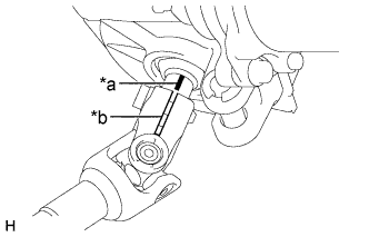 |
| *a | Marking (Pink) |
| *b | Slit |
| 9. INSTALL STEERING SLIDING YOKE SUB-ASSEMBLY |
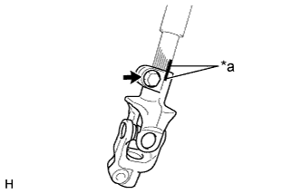 |
Align the matchmarks on the No. 2 steering intermediate shaft assembly and the steering sliding yoke and provisionally install them with the bolt.
| *a | Matchmark |