Home › Vehicle Interior › SUPPLEMENTAL RESTRAINT SYSTEMS › AIRBAG SYSTEM (for Sedan)

AIRBAG SYSTEM (for Sedan) > DIAGNOSIS SYSTEM


CHECK DLC3
  1. Check the DLC3 (Click here).


SYMPTOM SIMULATION

HINT:
The most difficult case in troubleshooting is when no symptoms occur. In such cases, a thorough customer problem analysis must be carried out. Then the same or similar conditions and environment in which the problem occurred in the customer's vehicle should be simulated. No matter how experienced or skilled a technician may be, if he proceeds to troubleshoot without confirming the problem symptoms, he will likely overlook something important and make a wrong guess at some points in the repair operation.
This leads to a standstill in troubleshooting.


    H100146E01
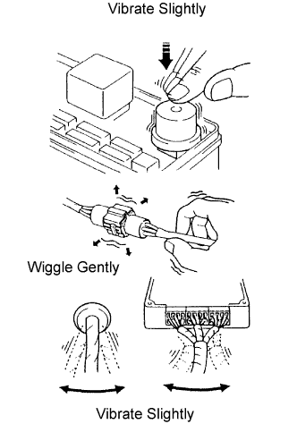
  1. Simulation method: When vibration seems to be the major cause

    HINT:
    Perform this method only during the primary check period (for approximately 6 seconds after the ignition switch is turned to the on position).


    1. Use your finger to slightly vibrate the part of the sensor considered to be the problem cause, and check whether the malfunction recurs.

      HINT:
      Wiggling the relays too strongly may result in open relays.

    2. Gently wiggle the connector.

    3. Slightly shake the wire harness vertically and horizontally.
      The connector joint and fulcrum of the vibration are the major areas to be checked thoroughly.

FUNCTION OF SRS WARNING LIGHT
  1. Primary check

    1. Turn the ignition switch to the lock position. Wait for at least 2 seconds, then turn the ignition switch to the on position. The SRS warning light comes on for approximately 6 seconds and the SRS airbag system diagnosis (including the seat belt pretensioner) is performed.

      HINT:
      If any malfunctions are detected during the primary check, the SRS warning light remains on even after the primary check period has elapsed.

  2. Constant check

    1. After the primary check, the center airbag sensor assembly constantly monitors the SRS airbag system for trouble.

      HINT:
      If any malfunctions are detected during the constant check, the center airbag sensor assembly functions as follows:
      1. The SRS warning light comes on.
      2. The SRS warning light goes off, and then comes on again. This blinking pattern indicates a source voltage drop. The SRS warning light goes off 10 seconds after the source voltage returns to normal.

  3. Review

    1. When the airbag system is normal:
      The SRS warning light comes on only during the primary check period (for approximately 6 seconds after the ignition switch is turned to the on position).

    2. When the airbag system malfunctions:

      1. The SRS warning light blinks after the primary check period has elapsed.
      2. The SRS warning light goes off after the primary check, but comes on again during the constant check.
      3. The SRS warning light remains off even after the ignition switch is turned from lock to on. However, if malfunctions such as an open circuit have occurred in the wire harness between the meter and ECU, the warning light comes on 10 seconds after the ignition switch is turned on.

      HINT:
      The center airbag sensor assembly keeps the SRS warning light on if any malfunctions have been detected in the airbag system.


SRS WARNING LIGHT CHECK


    C093955E01
  1. Turn the ignition switch to the on position, and check that the SRS warning light comes on for approximately 6 seconds (primary check).

  2. Check that the SRS warning light goes off approximately 6 seconds after the ignition switch is turned to the on position (constant check).

    HINT:
    When any of the following symptoms occur, refer to the Problem Symptoms Table (Click here).
    1. The SRS warning light comes on occasionally, after the primary check period has elapsed.
    2. Even when the SRS warning light comes on, no DTCs are set.
    3. Even when the ignition switch is turned from the lock to on position, the SRS warning light remains off.


CHECK PASSENGER AIRBAG ON/OFF INDICATOR


    C241480E01
  1. Turn the ignition switch to ON.

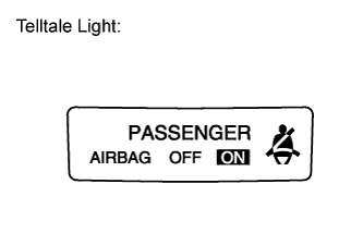
  2. Check that the passenger airbag ON/OFF indicator ("ON" and "OFF") comes on for approximately 4 seconds, then goes off for approximately 2 seconds.

    HINT:
    Refer to the table in the previous step regarding the passenger airbag ON/OFF indicator when the ignition switch is turned to ON and approximately 6 seconds have passed.


SRS CONNECTORS


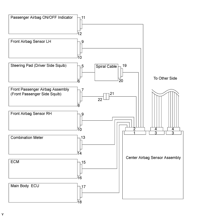
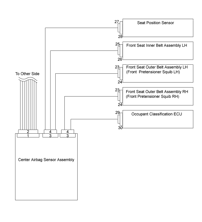
  1. SRS connectors are located as shown in the following illustration.


    H100937E05


    C281469E01


    No.
    Item
    Application
    (1)
    Terminal Twin-Lock Mechanism
    Connectors 2, 4, 9, 11, 13, 15, 19, 21, 22, 25, 27
    (2)
    Activation Prevention Mechanism
    Connectors 2, 4, 6, 8, 20, 22, 24
    (3)
    Half Connection Prevention Mechanism
    Connectors 9, 19, 21
    (4)
    Connector Position Assurance Mechanism
    Connector 9
    (5)
    Connector Lock Mechanism (1)
    Connectors 5, 7, 23
    (6)
    Connector Lock Mechanism (2)
    Connectors 2, 4
    (7)
    Improper Connection Prevention Lock Mechanism
    Connectors 1, 3


  2. H045308E01
  3. All connectors in the SRS except the seat position sensor connector and the occupant classification ECU connector are colored yellow to distinguish them from other connectors. Some connectors have special functions, and are specially designed for the SRS. These connectors use durable gold-plated terminals, and are placed in the locations shown above to ensure high reliability.

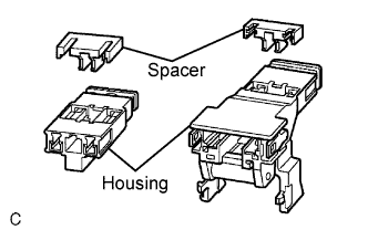
    1. Terminal twin-lock mechanism:
      Each connector is a two-piece component consisting of a housing and a spacer. This design enables the terminal to be locked securely by two locking devices (the retainer and the lance) to prevent the terminals from becoming disconnected.


    2. Activation prevention mechanism:
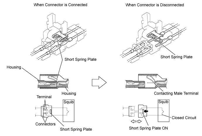
      Each connector contains a short spring plate. When the connector is disconnected, the short spring plate creates a short circuit by automatically connecting the positive (+) and negative (-) terminals of the squib.


      C127724E01


    3. Half connection prevention mechanism:
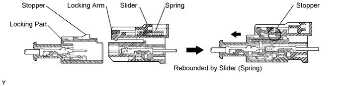
      If the connector is not completely connected, the connector is disconnected by the spring operation so that no continuity exists.


      H101827E01


    4. Connector position assurance mechanism:
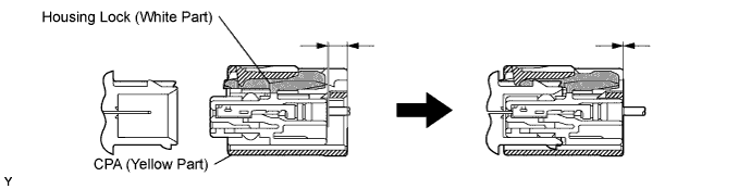
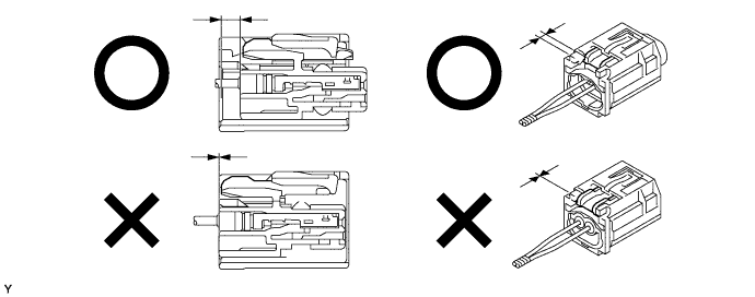
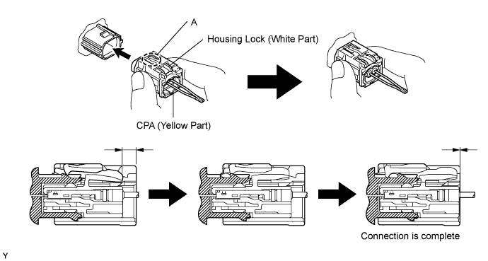
      The CPA (yellow part) slides, which completes the connector engagement, only when the housing lock (white part) is completely engaged.


      H101954E01


    5. Connector lock mechanism (1):
      Locking the connector lock button connects the connector.


      H101828E01


    6. Connector lock mechanism (2):
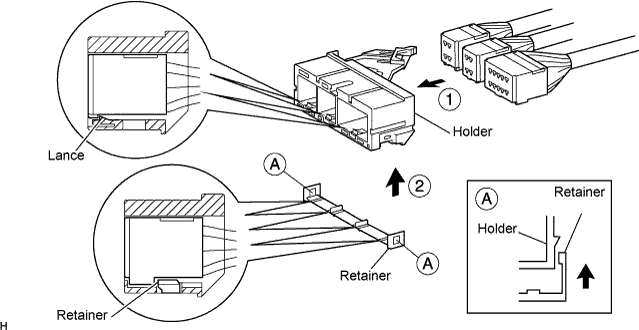
      Both the primary lock with holder lances and the secondary lock with a retainer prevent the connectors from becoming disconnected.


      C101082E02


    7. Improper connection prevention lock mechanism:
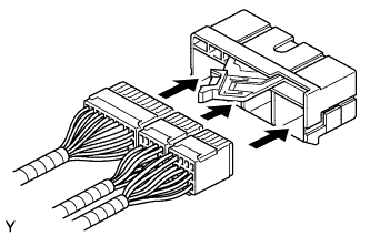
      When connecting the holder, the lever is pushed into the end by rotating around the A axis to lock the holder securely.


      H101830E01


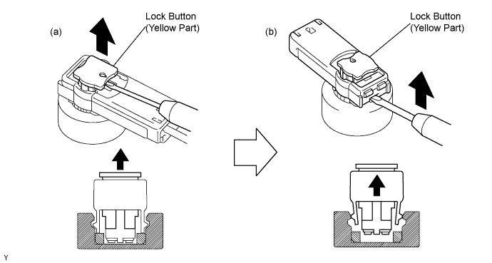
DISCONNECTION OF CONNECTORS FOR STEERING PAD, FRONT PASSENGER AIRBAG ASSEMBLY (SQUIB SIDE) AND FRONT SEAT OUTER BELT ASSEMBLY

HINT:
Tape the screwdriver tip before use.

  1. Release the lock button (yellow part) of the connector using a screwdriver.


  2. Insert the screwdriver tip between the connector and the base, and then raise the connector.


    H101832E01


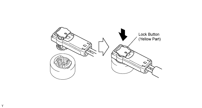
CONNECTION OF CONNECTORS FOR STEERING PAD, FRONT PASSENGER AIRBAG ASSEMBLY (SQUIB SIDE) AND FRONT SEAT OUTER BELT ASSEMBLY
  1. Connect the connector.


  2. Push the lock button (yellow part) of the connector down securely. (When locking, a click sound can be heard.)


    H101833E01


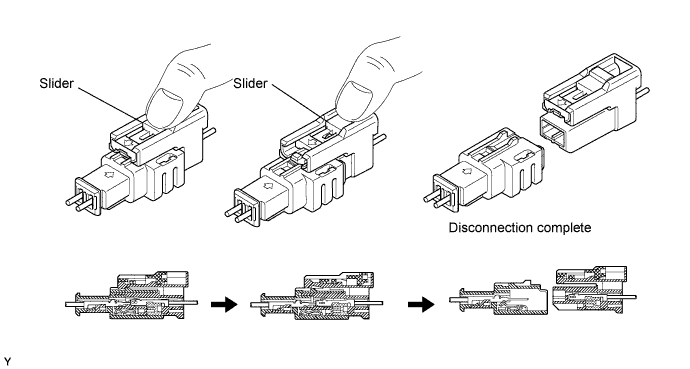
DISCONNECTION OF CONNECTORS FOR FRONT PASSENGER AIRBAG ASSEMBLY (INSTRUMENT PANEL WIRE SIDE)


  1. Place a finger on the slider, slide the slider to release the lock, and then disconnect the connector.


    H101836E01


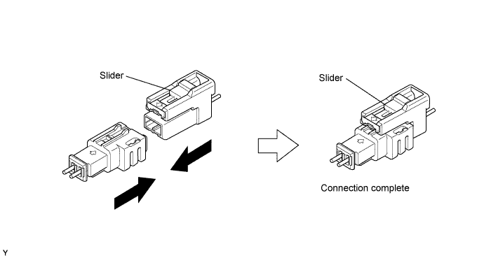
CONNECTION OF CONNECTORS FOR FRONT PASSENGER AIRBAG ASSEMBLY (INSTRUMENT PANEL WIRE SIDE)


  1. Connect the connector as shown in the illustration. (When locking, make sure that the slider returns to its original position and a click sound can be heard.)

    HINT:
    When connecting, the slider sides. Do not touch the slider while connecting, as this may result in an insecure fit.


    H101837E01


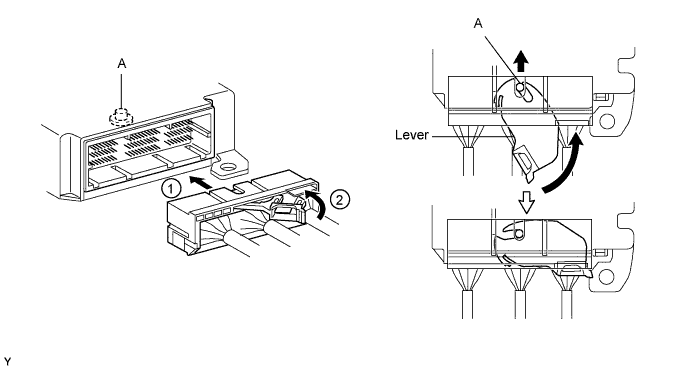
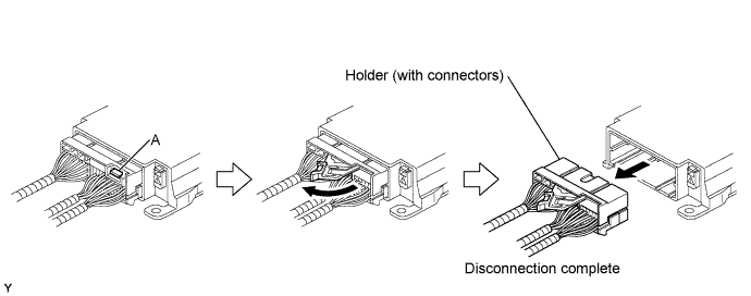
DISCONNECTION OF CONNECTORS FOR CENTER AIRBAG SENSOR ASSEMBLY


  1. Pull the lever by pushing part A as shown in the illustration and disconnect the holder (with connectors).


    H100822E02

    HINT:
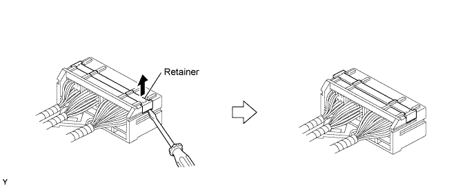
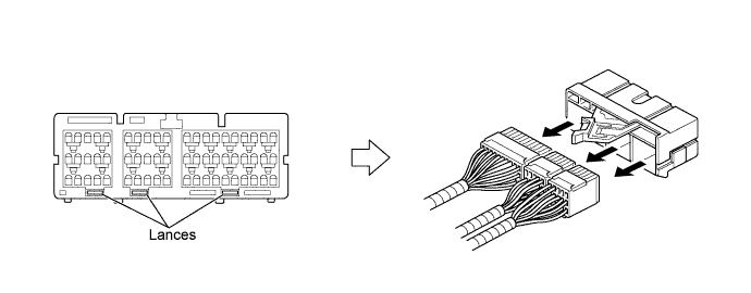
    Perform the following procedures when replacing the holder.


  2. Remove the holder.


    1. Using a screwdriver, unlock the retainer.


      H100823E01


    2. Release the fitting lances and remove the holder.


      H100824E01


  3. H100825
  4. Install the holder.

    1. Install the connectors into the holder. (When locking, a click sound can be heard.)

      HINT:
      The retainer is locked when the holder is connected.


CONNECTION OF CONNECTORS FOR CENTER AIRBAG SENSOR ASSEMBLY
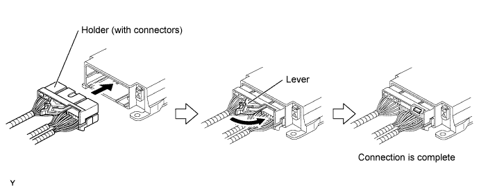
  1. Firmly insert the holder (with connectors) into the center airbag sensor assembly until it cannot be pushed any further.


  2. Push the lever to connect the holder (with connectors). (When locking, a click sound can be heard.)

    HINT:
    The holder slides into the center airbag sensor assembly when it is being connected. Do not hold the holder while connecting, as it may result in an insecure fit.


    H100903E01


DISCONNECTION OF CONNECTORS FOR FRONT AIRBAG SENSOR
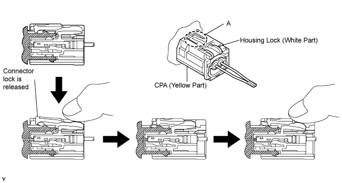
  1. Push down the housing lock (white part) and slide the CPA (yellow part). (At this time, the connector cannot be disconnected yet.)


  2. Push down the housing lock (white part) again and disconnect the connector.

    HINT:
    Do not push down part A shown in the illustration when disconnecting.


    H101952E01


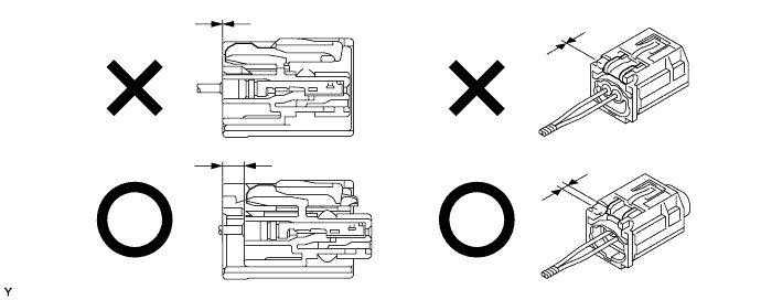
  3. After disconnecting the connector, check that the position of the housing lock (white part) is as shown in the illustration.


    H101953


CONNECTION OF CONNECTORS FOR FRONT AIRBAG SENSOR


  1. Before connecting the connectors, check that the position of the housing lock (white part) is as shown in the illustration.


    H101950


  2. Be sure to engage the connectors until they are locked. (When locking, make sure that a click sound can be heard.)

    HINT:
    When connecting them, the housing lock (white part) slides. Do not hold the housing lock (white part) and part A, as it may result in an insecure fit.


    H101951E01