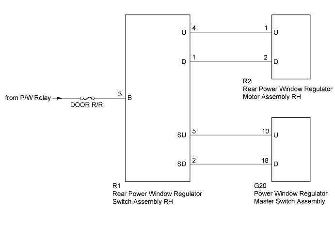
POWER WINDOW CONTROL SYSTEM (for Hatchback) > Rear Power Window RH does not Operate with Rear Power Window Switch RH |
| 1.INSPECT REAR POWER WINDOW REGULATOR SWITCH ASSEMBLY RH |
Inspect the rear power window regulator switch assembly RH (Click here).
|
| ||||
| OK | |
 |
| 2.INSPECT REAR POWER WINDOW REGULATOR MOTOR ASSEMBLY RH |
Inspect the rear power window regulator motor assembly RH (Click here).
|
| ||||
| OK | |
|
| 3.CHECK HARNESS AND CONNECTOR (REAR POWER WINDOW REGULATOR SWITCH ASSEMBLY RH - P/W RELAY) |
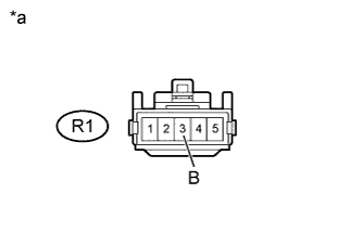 |
Disconnect the R1 rear power window regulator switch assembly RH connector.
Measure the voltage according to the value(s) in the table below.
| Tester Connection | Switch Condition | Specified Condition |
| R1-3 (B) - Body ground | Ignition switch ON | 11 to 14 V |
| *a | Front view of wire harness connector (to Rear Power Window Regulator Switch Assembly RH) |
|
| ||||
| OK | |
|
| 4.CHECK HARNESS AND CONNECTOR (REAR POWER WINDOW REGULATOR SWITCH ASSEMBLY RH - REAR POWER WINDOW REGULATOR MOTOR ASSEMBLY RH) |
Disconnect the R1 rear power window regulator switch assembly RH connector.
Disconnect the R2 rear power window regulator motor assembly RH connector.
Measure the resistance according the value(s) in the table below.
| Tester Connection | Condition | Specified Condition |
| R1-4 (U) - R2-1 (U) | Always | Below 1 Ω |
| R1-1 (D) - R2-2 (D) | Always | Below 1 Ω |
| R1-4 (U) - Body ground | Always | 10 kΩ or higher |
| R1-1 (D) - Body ground | Always | 10 kΩ or higher |
|
| ||||
| OK | |
|
| 5.CHECK HARNESS AND CONNECTOR (REAR POWER WINDOW REGULATOR SWITCH ASSEMBLY RH - POWER WINDOW REGULATOR MASTER SWITCH ASSEMBLY) |
Disconnect the R1 rear power window regulator switch assembly RH connector.
Disconnect the G20 power window regulator master switch assembly connector.
Measure the resistance according to the value(s) in the table below.
| Tester Connection | Condition | Specified Condition |
| R1-5 (SU) - G20-10 (U) | Always | Below 1 Ω |
| R1-2 (SD) - G20-18 (D) | Always | Below 1 Ω |
| R1-5 (SU) - Body ground | Always | 10 kΩ or higher |
| R1-2 (SD) - Body ground | Always | 10 kΩ or higher |
|
| ||||
| OK | ||
 | ||
| ||
