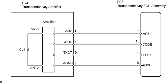
DTC B2796 No Communication in Immobiliser System |
DTC B2798 Communication Malfunction No. 2 |
| DTC No. | DTC Detection Condition | Trouble Area |
| B2796 | No communication |
|
| B2798 | Communication error | Key |
| 1.READ VALUE USING TECHSTREAM |
Connect a Techstream to the DLC3.
Turn the ignition switch to ON.
Turn the tester on.
Enter the following menus: Body Electrical / Immobiliser / Data List.
According to the display on tester, read the "Data List".
| Tester Display | Measurement Item/Range | Normal Condition | Diagnostic Note |
| Immobiliser | Immobiliser system status/ SET or UNSET | UNSET: Ignition switch ON SET: Without key | - |
|
| ||||
| OK | ||
 | ||
| ||
| 2.CHECK WHETHER ENGINE STARTS WITH OTHER KEYS |
Check whether the engine starts with the vehicle's other keys.
|
| ||||
| OK | ||
| ||
| ||
| 3.READ VALUE USING TECHSTREAM |
Connect a Techstream to the DLC3.
Turn the ignition switch to ON.
Turn the tester on.
Enter the following menus: Body Electrical / Immobiliser / Data List.
According to the display on tester, read the "Data List".
| Tester Display | Measurement Item/Range | Normal Condition | Diagnostic Note |
| Antenna Coil Status | Antenna coil condition/ NORMAL or FAIL | NORMAL: Antenna coil is normal FAIL: Antenna coil is malfunctioning | - |
|
| ||||
| OK | |
 |
| 4.CHECK HARNESS AND CONNECTOR (TRANSPONDER KEY ECU - TRANSPONDER KEY AMPLIFIER) |
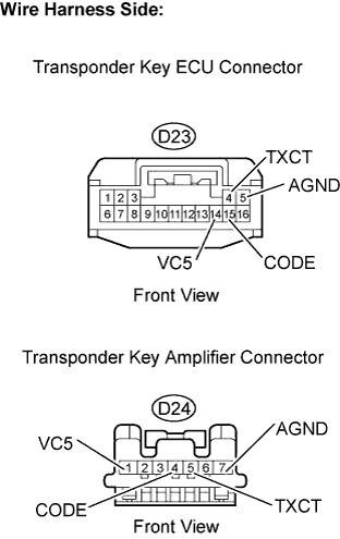 |
Disconnect the D23 transponder key ECU connector.
Disconnect the D24 transponder key amplifier connector.
Measure the resistance of the wire harness side connectors.
| Tester Connection | Specified Condition |
| D23-14 (VC5) - D24-1 (VC5) | Below 1 Ω |
| D23-15 (CODE) - D24-4 (CODE) | Below 1 Ω |
| D23-4 (TXCT) - D24-5 (TXCT) | Below 1 Ω |
| D23-5 (AGND) - D24-7 (AGND) | Below 1 Ω |
| D23-14 (VC5) or D24-1 (VC5) - Body ground | 10 kΩ or higher |
| D23-15 (CODE) or D24-4 (CODE) - Body ground | 10 kΩ or higher |
| D23-4 (TXCT) or D24-5 (TXCT) - Body ground | 10 kΩ or higher |
| D23-5 (AGND) or D24-7 (AGND) - Body ground | 10 kΩ or higher |
Reconnect the D23 transponder key ECU connector.
Reconnect the D24 transponder key amplifier connector.
|
| ||||
| OK | |
|
| 5.REPLACE TRANSPONDER KEY AMPLIFIER |
After replacing the transponder key amplifier with a normally functioning amplifier, check that the engine starts.
|
| ||||
| OK | ||
| ||
| ||

