REAR AXLE BEAM (for Sedan) > REMOVAL |
| 1. REMOVE REAR WHEEL |
| 2. DRAIN BRAKE FLUID |
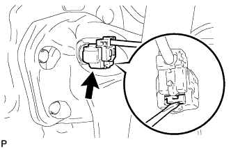
| 3. SEPARATE SKID CONTROL SENSOR WIRE (w/ ABS) |
|
Using a screwdriver, remove the claw of the connector lock portion and disconnect the skid control sensor wire connector.
| 4. SEPARATE REAR NO. 4 BRAKE TUBE |
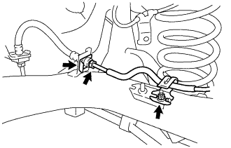 |
Using a 10 mm union nut wrench, disconnect the rear No. 4 brake tube while holding the rear flexible hose LH with a wrench.
Remove the clip and separate the rear flexible hose LH from the rear axle beam.
Remove the nut and separate the rear No. 4 brake tube from the rear axle beam.
| 5. SEPARATE REAR NO. 3 BRAKE TUBE |
| 6. SEPARATE NO. 3 PARKING BRAKE CABLE ASSEMBLY |
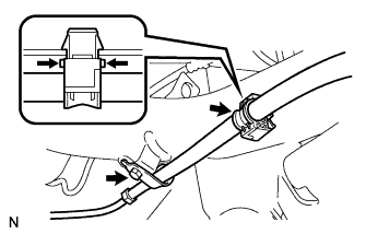 |
Using pliers, pinch both ends of the claw of the cable clamp and flex the clamp to remove it.
Remove the bolt and separate the No. 3 parking brake cable assembly from the axle beam.
Remove the cable clamp from the No. 3 parking brake cable assembly.
| 7. SEPARATE NO. 2 PARKING BRAKE CABLE ASSEMBLY |
| 8. REMOVE REAR BRAKE DRUM SUB-ASSEMBLY |
Release the parking brake and remove the rear brake drum.
If the rear brake drum cannot be removed easily, perform the following procedure.
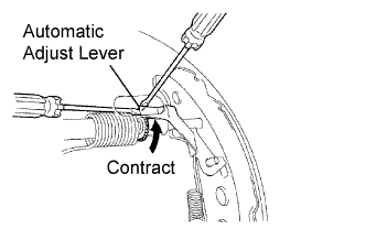 |
Remove the hole plug and insert a screwdriver through the hole into the backing plate, and hold the automatic adjust lever away from the adjuster.
Using another screwdriver, contract the brake shoe by turning the adjusting bolt.
| 9. REMOVE REAR AXLE HUB AND BEARING ASSEMBLY LH |
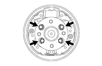 |
Remove the 4 bolts and remove the axle hub and bearing from the axle beam.
| 10. REMOVE REAR AXLE HUB AND BEARING ASSEMBLY RH |
| 11. LOOSEN REAR AXLE BEAM |
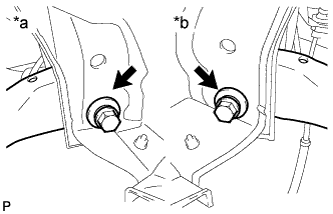 |
Loosen the 2 bolts.
| *a | RH Side |
| *b | LH Side |
| 12. REMOVE REAR COIL SPRING LH |
Support the spring seat of the rear axle beam with an engine lifter using 2 wooden blocks as shown in the illustration.
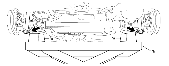
| *a | Wooden Block | *b | Engine Lifter |
Remove the 2 bolts while holding the 2 nuts and separate the rear axle beam from the rear shock absorber assemblies LH and RH.
Slowly lower the rear axle beam with an engine lifter and 2 wooden blocks.
Remove the rear coil spring LH, rear upper coil spring insulator LH and the rear lower coil spring insulator LH.
Slowly jack up the rear axle beam with an engine lifter using 2 wooden blocks, and temporarily tighten the rear axle beam to the rear shock absorber assemblies LH and RH with the 2 bolts and 2 nuts.
| 13. REMOVE REAR COIL SPRING RH |
| 14. REMOVE REAR AXLE BEAM |
Support the rear axle beam with an engine lifter using 2 wooden blocks and the 2 plate lift attachments or equivalent tools as shown in the illustration.
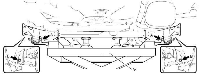
| *a | Plate Lift Attachment | *b | Wooden Block |
| *c | Engine Lifter | - | - |
Remove the 2 bolts A and 2 nuts while holding the 2 nuts and separate the rear axle beam from the rear shock absorber assemblies LH and RH.
Remove the 2 bolts B and the rear axle beam from the body.
| 15. REMOVE REAR AXLE CARRIER BUSH LH |
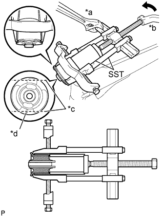 |
Place a matchmark on the rear axle beam with it aligned with the alignment mark.
| *a | Hold |
| *b | Turn |
| *c | Bend Portions |
| *d | Alignment Mark |
Using a chisel and hammer, bend the 2 portions of the bush rib.
Using SST, remove the rear axle carrier bush LH from the rear axle beam.
| 16. REMOVE REAR AXLE CARRIER BUSH RH |