 |
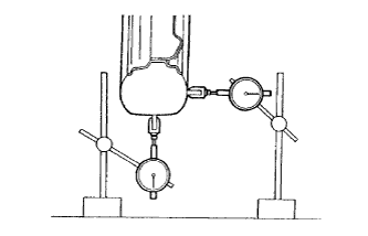
Using a dial indicator, check the tire runout.
- Tire Runout:
Vertical 1.4 mm (0.0551 in.) or less Lateral 2.0 mm (0.0787 in.) or less
REAR WHEEL ALIGNMENT (for Hatchback) > INSPECTION |
| 1. INSPECT TIRES |
Check the tires for wear and proper inflation pressure.
| Tire Size | Front kPa (kgf/cm2, psi) | Rear kPa (kgf/cm2, psi) |
| P175/65R15 84H | 230 (2.3, 33) | 230 (2.3, 33) |
| P195/50R16 83V | 220 (2.2, 32) | 200 (2.0, 29) |
| 185/60R15 84H | 220 (2.2, 32) | 220 (2.2, 32) |
|
Using a dial indicator, check the tire runout.
| Vertical | 1.4 mm (0.0551 in.) or less |
| Lateral | 2.0 mm (0.0787 in.) or less |
| 2. MEASURE VEHICLE HEIGHT |
Bounce the vehicle up and down at the corners to stabilize the suspension.
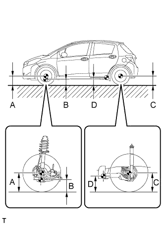 |
Measure the vehicle height.
| Tire Size | Front A - B | Rear C - D |
| P175/65 R15 | 97 mm (3.82 in.) | 32 mm (1.26 in.) |
| P195/50 R16 | 101 mm (3.98 in.) | 32 mm (1.26 in.) |
| 185/60 R15 | 69 mm (2.72 in.) | 4.0 mm (0.157 in.) |
| 3. INSPECT CAMBER |
Install the camber-caster-kingpin gauge and position the rear wheel on the turning radius gauge.
Inspect the camber.
| Tire Size | Camber | Right - left Difference |
| P175/65 R15 | -0°57' +/- 30' (-0.95° +/- 0.5°) | 0°30' (0.5°) |
| P195/50 R16 | -0°57' +/- 30' (-0.95° +/- 0.5°) | 0°30' (0.5°) |
| 185/60 R15 | -0°54' +/- 30' (-0.90° +/- 0.5°) | 0°30' (0.5°) |
| 4. INSPECT TOE-IN |
Bounce the vehicle up and down at the corners to stabilize the suspension.
Release the parking brake and move the shift lever to N.
Push the vehicle straight ahead approximately 5 m (16.4 ft.). (Step A)
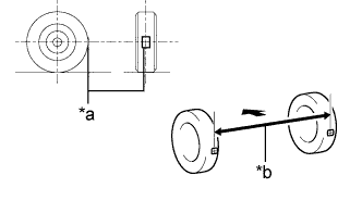 |
Put tread center marks on the rearmost points of the rear wheels and measure the distance between the marks (dimension B).
| *a | Tread Center Mark |
| *b | Dimension B |
 | Front of the Vehicle |
Slowly push the vehicle straight ahead to cause the rear wheels to rotate 180°. Use the rear tire valve as a reference point.
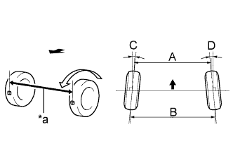 |
Measure the distance between the tread center marks on the front of the rear wheels (dimension A).
| *a | Dimension A |
| Front of the Vehicle |
| Tire Size | Specified Condition |
| P175/65 R15 | B - A: 3.9 +/- 3.0 mm (0.154 +/- 0.118 in.) |
| C + D: 0°22' +/- 15' (0.37° +/- 0.25°) | |
| P195/50 R16 | B - A: 3.8 +/- 3.0 mm (0.150 +/- 0.118 in.) |
| C + D: 0°22' +/- 15' (0.37° +/- 0.25°) | |
| 185/60 R15 | B - A: 2.7 +/- 3.0 mm (0.106 +/- 0.118 in.) |
| C + D: 0°15' +/- 15' (0.25° +/- 0.25°) |
| 5. PERFORM YAW RATE AND ACCELERATION SENSOR CALIBRATION |