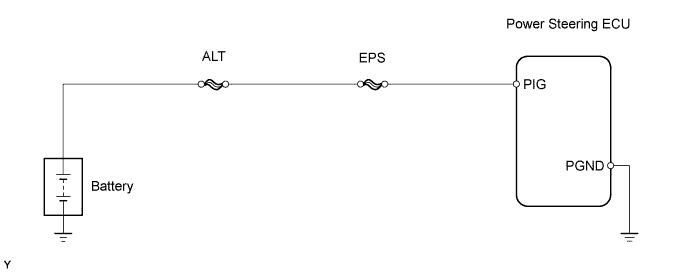
DTC C1552/52 PIG Power Source Circuit |
DTC C1553/53 When Resetting Voltage, Vehicle is Being Driven |
DTC C1554/54 EPS Relay Circuit |
DTC C1555/55 EPS Motor Relay Circuit |
| DTC No. | DTC Detection Condition | Trouble Area |
| C1552/52 | PIG power source circuit malfunction |
|
| C1553/53 | Abnormal overvoltage |
|
| C1554/54 | Power source relay circuit malfunction |
|
| C1555/55 | Motor relay circuit malfunction |
|
| 1.READ VALUE USING TECHSTREAM |
Connect a Techstream to the DLC3.
Turn the ignition switch to ON.
Turn the Techstream on.
Enter the following menus: Chassis / EMPS / Data List.
Select the item "PIG Power Supply" in the Data List and read the value displayed on the Techstream.
| Tester Display | Measurement Item/Range | Normal Condition | Diagnostic Note |
| PIG Power Supply | Power source voltage to activate motor: Minimum: 0.0000 V, Maximum: 20.1531 V | 11 to 14 V: Always | - |
|
| ||||
| NG | |
 |
| 2.INSPECT FUSE (EPS FUSE) |
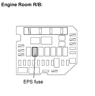 |
Remove the EPS fuse from the engine room R/B.
Measure the resistance of the fuse.
|
| ||||
| OK | |
|
| 3.CHECK HARNESS AND CONNECTOR (POWER STEERING ECU - BODY GROUND) |
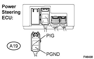 |
Disconnect the connector from the power steering ECU.
Measure the voltage and the resistance.
| Tester Connection | Condition | Specified Condition |
| PIG (A19-1) - Body ground | Always | 11 to 14 V |
| PGND (A19-2) - Body ground | Always | Below 1 Ω |
|
| ||||
| OK | |
|
| 4.INSPECT STEERING COLUMN ASSEMBLY (POWER STEERING MOTOR) |
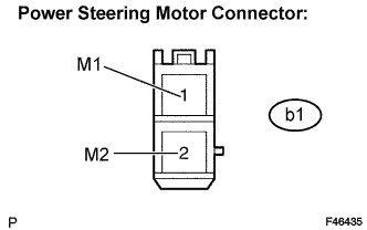 |
Disconnect the connector from the power steering ECU.
Measure the resistance.
| Tester Connection | Condition | Specified Condition |
| M1 (b1-1) - M2 (b1-2) | Always | 0.08 to 0.15 Ω |
| M1 (b1-1) - Body ground | Always | 1 MΩ or higher |
| M2 (b1-2) - Body ground | Always | 1 MΩ or higher |
|
| ||||
| OK | ||
 | ||
| ||
