KNOCK SENSOR (for Sedan) > INSTALLATION |
| 1. INSTALL KNOCK SENSOR |
|
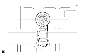
Install the knock sensor with the nut as shown in the illustration.
Connect the knock sensor connector.
| 2. INSTALL INTAKE MANIFOLD |
Install a new gasket onto the intake manifold.
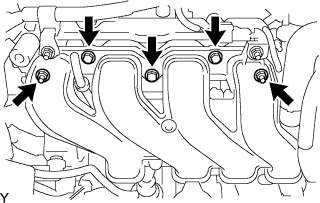 |
Install the intake manifold with the 3 bolts and 2 nuts.
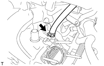 |
Connect the union to connector tube hose.
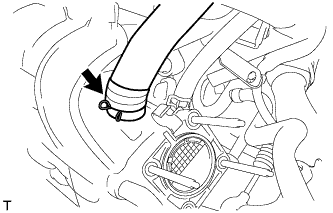 |
Connect the ventilation hose.
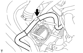 |
Install water by-pass hose No. 2.
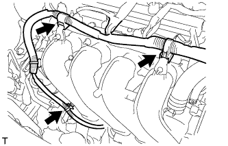 |
Install the engine wire harness onto the intake manifold.
| 3. INSTALL THROTTLE WITH MOTOR BODY ASSEMBLY |
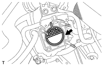 |
Install a new gasket onto the intake manifold.
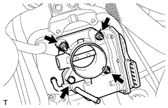 |
Install the throttle with motor body assembly using the bolt and 3 nuts.
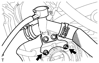 |
Install the water filler sub-assembly with hose using the 2 nuts.
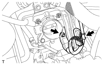 |
Install the wire harness with bracket using the nut.
Connect the throttle with motor body assembly connector.
| 4. CONNECT WATER BY-PASS HOSE NO. 2 |
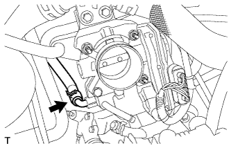 |
Connect water by-pass hose No. 2.
| 5. CONNECT WATER BY-PASS HOSE |
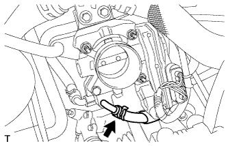 |
Connect the water by-pass hose.
| 6. INSTALL AIR CLEANER CAP SUB-ASSEMBLY WITH AIR CLEANER HOSE NO. 1 |
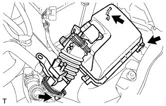 |
Install air cleaner cap sub-assembly with air cleaner hose No. 1.
Tighten the hose clamp to the specified torque.
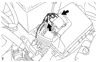 |
Connect the wire harness clamp and mass air flow meter connector.
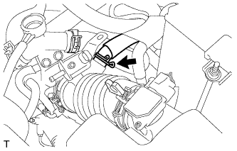 |
Connect ventilation hose No. 2.
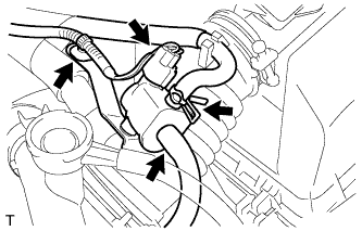 |
Connect the vacuum switching valve assembly connector and wire harness clamp.
Connect fuel vapor feed hose No. 1 and fuel vapor feed hose No. 2 to the vacuum switching valve assembly.
| 7. CONNECT CABLE TO NEGATIVE BATTERY TERMINAL |
| 8. ADD ENGINE COOLANT |
Tighten the radiator drain cock plug by hand.
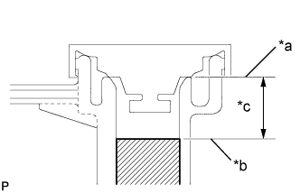 |
Slowly fill the radiator with TOYOTA Super Long Life Coolant (SLLC) from the water filler. (Coolant level should be within 20 mm (0.787 in.) from the filler tube end.)
| *a | Filler Tube End |
| *b | Coolant Level |
| *c | 20 mm (0.787 in.) |
| Transaxle Type | Coolant Capacity |
| Automatic Transaxle | 4.7 liters (5.0 US qts, 4.4 Imp. qts) |
| Manual Transaxle | 4.8 liters (5.1 US qts, 4.5 Imp. qts) |
Remove the reserve tank cap.
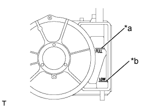 |
Slowly pour coolant into the radiator reserve tank assembly until it reaches the full line.
| *a | Full Line |
| *b | Low Line |
Install the water filler cap sub-assembly securely.
Install the reserve tank cap.
Bleed air from the cooling system.
Warm up the engine until the thermostat opens.
While the thermostat is open, circulate the coolant for several minutes.
Stop the engine and wait until the coolant cools down.
Recheck the coolant level inside the radiator reserve tank assembly. If it is below the full level, add coolant.
| 9. CHECK FOR ENGINE COOLANT LEAKAGE |
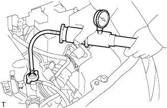 |
Fill the radiator assembly with engine coolant, and attach a radiator cap tester.
Pump the tester to 118 kPa (1.2 kgf/cm2, 17.1 psi), and then check that the pressure does not drop.
If the pressure drops, check the hoses, radiator assembly and water pump assembly for leaks. If there are no signs or traces of external engine coolant leaks, check the heater core, cylinder block and head.
| 10. INSTALL CYLINDER HEAD COVER NO. 2 |
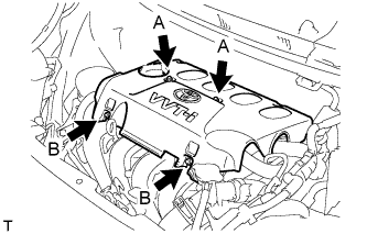 |
Tighten the 2 A nuts, then the 2 B nuts.